Also:
CAUTION: The Linistepper requires suitable, large heatsinking. Such as standard chunky aluminum/alloy heatsinks with fins. For additional heat dissipation use a bigger heatsink with extra fins, or even add a small computer fan to remove the excess heat. (steel is not a suitable heatsink, the angle bracket is NOT a heatsink.)
The connector furthest from the heatsink (on the left) is the control connector.
| Linistepper (Version 2 or higher) Starting with Pin 1 on the 2x5 header:
Pin 1 /Enable (low = Pin 3 Direction input (hi = reverse) Pin 5 Step input (step on positive edge) Pin 7 Ground for Motor and driver (common), Pin 9 +5VDC regulated All even pins are grounded to interface common
* On the V3, /Enable high disables the driver. Low power hold is automatic.
|
Original Linistepper (Version 1) Starting closest to the diodes, the 7 pins are: * GND (Ground) (also attached to the motor ground) * +5v regulated (power for PIC chip) * Step input (new step on + going edge) * Direction input (hi = reverse) * Low power (lo = low power) * Mode 0 * Mode 1 (these select the stepping mode as shown in this table) Mode 0 Mode 1 Result 0(GND) 0(GND) 200 (full step) 1(+5v) 0(GND) 400 (high-torque half step) 0(GND) 1(+5v) 1200 (microstep 6th) 1(+5v) 1(+5v) 3600 (microstep 18th) Note: The mode 1 pin is at the corner of the printed circuit board. |
Wiring: For information on how to connect the Linistepper (or multiple Linisteppers) to a PC parallel port, see: http://www.piclist.com/io/stepper/linistep/faq.htm#37570.4504050926 or try our Linistepper "4 AXIS / Mode / 555 / PWR" kit
Software: Setup instructions are available for TurboCNC , Mach 3, or EMC
Timing: The Step pulse must be at least 3uS long and must come 1uS after any change in the Direction. Stepping rates of more than 50,000 steps per second are supported. Enable should just be left on unless the unit will not be moving for several seconds at least. When enable is turned on, at least a second should be allowed before attempting movement.
The connector closest to the heatsink is the power and motor connector. The Motor Power positive main voltage should be supplied with 4 to 10 volts more than the maximum rated voltage of your motor. For example, a 5 volt motor would run nicely on a 12 volt supply; the driver will stay cooler on a 9 volt supply, and the motor will turn up to a somewhat higher maximum RPM with a 15 volt supply.
The 7 pins are divided into 2 for the power connector, and 5 for the motor, starting closest to the resistors;
|
Motor Power (motor rating + 4v; up to 35v max) | |
|
||
|
|
||
|
Motor Leads (unipolar motor) |
|
|
||
|
||
|
||
|
||
*Note: On the Version 1 PCB, "Motor + (common)" and "Positive main voltage" were provided as two seperate pin, but they have always been connected together on the PCB; these are the same electrical connection. On the Version 2 PCB, these are combined into one screw terminal, which can accept two wires, one from the power supply, one to the motor common. On the Version 3 PCB, there is a seperate screw terminal for motor power in, and motor common out, although these are the same electrically.
Don't disconnect any motor wires with the power turned on!
Important! All 5 input pins MUST be connected to something, ie to a digital output or tied to 0v(GND) or +5v. DO NOT leave inputs floating!
Most of this is quite obvious:
First check that the regulated +5v is there, then motor voltage which is normally between 4v and 35v.
Assuming you are clocking the step input and you have the low power pin held hi (full power) and you have the motor common + wire connected properly there is one likely reason that the motor does not turn.
Try swapping one A wire with one B wire, you may have connected the motor phasing wrong. If you have the phasing wrong, the motor will tend to sit there and "wobble" or "buzz". :o)
If the motor turns, but in the wrong direction, you only need to swap the two A wires with each other.
Don't disconnect any motor wires with the power turned on!
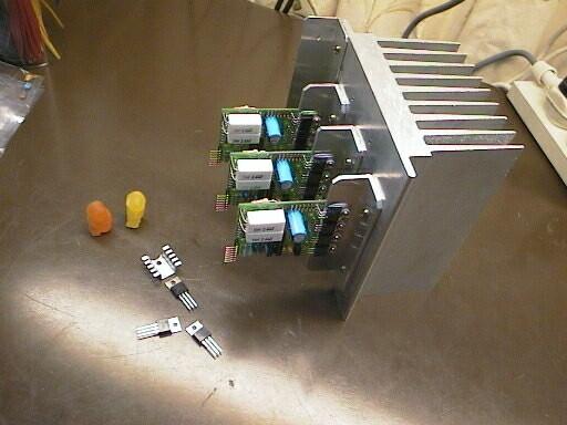 Jelly Baby Engineers: "Heatsink? You call that a Heatsink??
THAT'S A HEATSINK!!"
Jelly Baby Engineers: "Heatsink? You call that a Heatsink??
THAT'S A HEATSINK!!"
The linistepper is a linear driver and will dissipate quite a lot of heat IF you have a psu voltage that is a lot higher than the motor coil voltage.
The difference between supply voltage and motor voltage is lost as wasted heat energy.
When you only need low speed performance, ie motor speeds under 4 revs/second, you can use low supply voltage and minimise heat and power loss. The motor will perform well at low speeds, with the linear smoothed microstepping advantages giving better performance than many chopped drivers that are not microstepped, and similar heat performance.
To get minimum heating and power loss you need to use the minimum supply voltage that will give full current with your chosen motor.
Finding the max efficiency point is quite easy:
In most stepper uses a motor speed of 4 revs/second etc is all you require, especially when microstepping gives increased positioning resolution AND increased low speed torque. You no longer need excessive gearing to get resolution and many apps no longer need high speeds. Using a psu of only 3v above the motor voltage will give decent motor performance and greatly reduced motor heating.
If you need better high speed performance you will need to use a higher psu voltage. How much higher depends on the torque needed at the highest speeds. Here's a bit of theory about this:
Stepper motor coils are magnetic and have inductance. To put this very simply, inductance means that it takes TIME to build a magnetic field in the coil, and larger inductance means that the change from no magnetic field to full magnetic field takes longer than a low inductance motor. Inductance is closely related to how many turns of wire so motors that have finer wire and more turns will have higher inductances.
Like this:
fine wire = high volts/low amps = high inductance = slow motor
thick wire = low volts/high amps = low inductance = fast motor
Many people instantly assume that low inductance motors are better, and indeed these days they are more common with new motors. But low inductance motors are NOT always the best choice.
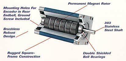
The linistepper was designed to be well suited to many older stepper motors, most of which are high inductance. These motors are often found at VERY CHEAP prices from "surplus" sellers.
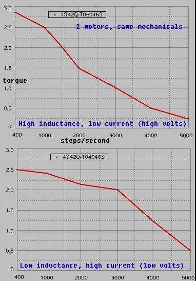
Apart from that big advantage, high inductance motors are usually more efficient magnetically and often give higher holding torque for the same coil wattage. These charts are from a manufacturers website. Motors are the same apart from winding type. Holding torque is 20% more for the high inductance motor, and even at 400 steps/sec (2 revs/sec) the high inductance motor still has 8% more torque than the "fast" motor.
The best advantage of high inductance motors is that because of their inability to change current rapidly they are a better choice when you mainly need low speeds. They are smoother and produce less excitation energy at low speeds as they change from step to step more gently. I often see people struggling with resonance problems, and find they are using low inductance motors on systems that never exceed a few revs/second! Many of the suppliers are at fault here, and even the educational institutions often teach that low inductance motors and chopper drives are "superior". Superiority MUST be evaluated by application. :o)
In any case for the linistepper (or any linear driver) it is better to use the higher impedance motors, simply because they require less current.
The amount of PSU voltage you need is determined by the application. In most cases a voltage of 3x the rated motor voltage will give decent performance through the main resonances up to 10 or 15 revs/second. I have one machine here with 5v 1A motors giiving good power at speeds up to 10 revs/second, and an 18v PSU. I also ran an old low-speed "pancake" type 5v 400mA motor at a speed of 80 revs/second with the linistepper and 25v psu... It screamed!
Increasing the PSU voltage increases the torque at high speeds, but also increases heat and power waste. You will get better overall performance by choosing a motor with lower current and higher inductance. However if your application really does need high torque at very high speeds you will need a chopper drive and low inductance motor.
Only use higher PSU voltage if you REALLY need high speed power. In most cases the problems users experience relate to resonance at lower speeds. Low speed resonance is reduced by using a lower PSU voltage!
On a system where low speed resonance is a problem (like a belt driven setup or any lightweight system) you will find resonance is greatly reduced by using the lowest possible PSU voltage, where the motor inductance is maximised in effect. This gives the smoothest possible step transitions, and slow resonant systems are one situation where a correctly set up linear and "old fashioned" high inductance motor will really out-perform the modern chopper driver.
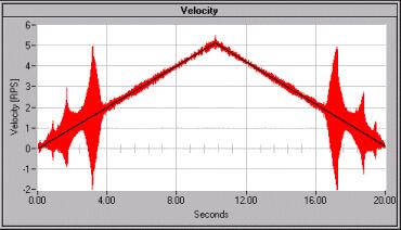
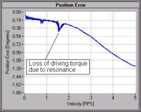
Here are two charts showing typical motor resonances, these are fairly typical high inductance motors and show how resonance is generally not a problem after about 2 revs/second. With low inductance motors you may still be having bad resonance problems even as high as 20 revs/ second.
Running your system with a variable voltage psu and testing for motor speed and resonances you can determine the optimum psu voltage where smoothest operation and less heat (low psu voltage) is obtained at a psu voltage high enough to still give the desired torque at higher speeds.
The inputs to the linistepper can be connected to a PC printer port, or other 5v digital device. Be aware that the PC and the stepper motor PSU and the +5v regulator must all share the same ground. As PC's have a grounded case and PSU this is rarely a problem.
Some PC printer (parallel) ports only put out 3.5v when at logic "high". The linistepper inputs require over 4v input for a logic high, and under 1v to input a logic low. In some rare cases the PC printer port will not output >4v and you may need to add 1000 ohm resistors from each of the input pins to 5v. A simple test with a voltmeter should confirm that your PC port voltages are within spec.
The linistepper uses a + going step clock. Each step occurs when the step input goes from 0v to 5v. Set your CNC software for + going step. Likewise set the direction input to give the correct direction motor rotation. If you can't change the direction in your CNC software setup you can swap the two motor A phase wires with each other.
The linistepper, Version 1 only, provides the feature where you can change between step modes on the fly, ie as the motor is running. This allows you to use 200 or 400 steps for fast transits and then change to 1200 or 3600 steps for final positioning. Version 2 and 3 require that the driver be disabled (/Enable high) before mode changes will have effect.
This is an advanced feature and has some drawbacks, the main one is that your controlling software must be responsible to track the change in step resolution. I don't suggest using this feature unless you are sure that you can do this without losing track of the step position.
The basic rule:
Make sure the driver is on a valid microstep for the mode you set, BEFORE
you change to that mode.
ie; if you are in 3600 step mode and you want to change to 1200 step mode, you must first be on a valid microstep for the 1200 step mode. These valid steps are every 3rd microstep, so when changing from 3600 mode to 1200 mode you must be on the 0,3,6,9, etc step.
The valid steps for each mode are shown here:
Mode    Valid steps
3600    all 72 microsteps;  0 to 71
1200    every 3rd step (mod 3) steps; 0,3,6,9 up to 69
400     only 8 valid steps;   4, 13, 22, 31, 40, 49, 58, 67
200     only 4 valid steps;   9, 27, 45, 63
So if you are changing from 3600 step mode to 200 step mode, you must first position the motor on either the 9, 27, 45 or 63 microstep, as these are the only valid steps for the 200 mode, and THEN you can change to the 200 step mode.
If you don't position on a valid step before changing mode, the driver will LOSE or GAIN steps when it re-synchronises in the new mode. This results in a step error, which is also continued when the mode is changed back or changed again.
When the linistepper powers up, it is on step 0. The user software is required to count steps forward and back and always track which of the 72 possible steps the driver is at. If your CNC software can't do this modulus 72 tracking then don't change modes on the fly!
There are further complications starting in 200 or 400 modes. If starting in either of these modes, the step will be 0, which is a non-valid step. The PIC will add 9 or 18 microsteps for each step signal. The driver will be on invalid steps until the cycle loops. That will occur in one step if the first step is backward, otherwise it will take 4 steps forward in 200 mode, or 8 steps forward in 400 mode to re-synchronise onto valid steps.
So, do not change modes on the fly unless;
It is possible to re-write the PIC software to address these issues and keep track of the step offsets internally, but I really can't be bothered as the modulus 72 tracking still needs to be done in the OTHER software (the PC side). :o)
-end
Questions:
Hi there,
I am really struggling here. I have built the linnistepper board and everything seems to be working well at first but the motor seems like it has it's own mind. It will for instance ignore for a while the direction signal and then obey it. Sometimes it won't step. I am sort of sure the phases is right but what else can I check. It sort of seems like it misses one phase and does not have the power to start stepping or it just do not have the right sequence to turn in the correct direction. I have tried it with two motors . I am driving it with a little system for an electronic dividing head.
Can the motor still step if one phase is missing?
Regards
Nic
James Newton of Massmind replies: It's very easy to check: Just put the Linistepper in to full step mode, and use a meter to check the motor leads after ONE step pulse. You should see a standard stepping pattern. If you don't it will show you where the problem is and then you can start looking back up the sequence of components from the PIC to the motor.+
Hello
Thanks a lot for this very nice project. I've built a linistep but used BD667s which have very similar characteristics as TIP122 except for a slightly lower maximum current. As diodes 1N4001s were used which i thought should be fast enough for the frequencies used here.
The stepper used is a Shinano Kenshi STH-39D213 with 200steps/5.2Ohm and is operated at 12V.
The correct wires were identified with a multimeter and the correct sequence with applying a small voltage at the 4 wires until the stepping sequence was correct.
The linistep does work so far but nowhere near optimal.At around 200 rev/min the stepper stops. I measured the current which the motor takes and it starts at about 0.3A at low speed and sinks below 60mA as the speed is increased.
The linistep is triggered by a NE555 circuit which generates impulses with near 50% duty cycle and up to 150kHz.
Does anyone see a problem with my setup? Any suggestions how to improve the performance?
I looked at the signals on pins 6 through 9 of the PIC. It was a square with 50% duty cycle on each of them. I would have thought that in 200 step mode each of the darlingtons should be switched on for 25% of the time, so the signals should have a duty cycle of 75% and not 50%. Is that correct?
Thanks a lot.
Metin
James Newton of Massmind replies: Sounds like a power supply problem. Check the current is more than double the per phase requirement and the voltage is at least a few volts more than the motors rated voltage. The 50% is due to high power half step mode. +
mparkolaias_dim-gmail- replies: Hello everyone, I recently found a STH-39D213 stepper motor and I can't find anything online about it's specs. Does anyone know how much torque it outputs? Thanks a lot.+
Hi, I just put an order in for one of your linisteppers... can't wait to get it. I looked at your circuit diagram as shown on the main page, I notice that you connected the 12V DC motor power supply pin to the 470 microF capacitor, which then runs to GND, forgive my poor electronics knowledge, but how is this going to supply 12V DC? Also, if I want to supply power from a separate power supply unit with a different Voltage from 12 V, can I connect it there, and disregard this 470 microF connection you drew on that circuit diagram?
James Newton of Massmind replies: The Motor power (12 or other) must be supplied by the user, in addition to the +5 logic power. The motor power should be at least a few volts over the rated voltage of the stepper motors and as much as 2 or perhaps 3 times as much as thier rated power, although more voltage means more heat in the drivers. The 4 Axis board provides an easy way to generate the +5 logic supply from the motor power as long as the motor power voltage is between 7 and 25 volts.+
As a newbie, I was wondering what values would I need to change R14-17 and R18-29 to allow me to run 5V 3Amps 400 step. Or could I just use 3 X 1ohm 5W res and cool them?
James Newton replies: See: Tuning the Linistepper for different motors, loads, and current in the section "Changing Current"; there is a little calculator that will tell you exactly what values you can use.+
James
Newton replies: That sounds like mid band resonance. The linistepper,
in microstepping modes, will have less of a problem with resonance, but there
are always some issues with vibration and resonance; you might want to look
into mechanical resonance damping.+
So if I have a stepper motor marked as 24 volt, 0.3 amp would this be considered a high inductance motor? What kind of performace loss would there be if it was powered by a lower voltage? Would it lose half of its torque? Application would be 1 rpm or less. Is the Linistepper capable of this?
Thanks,
Nathan
That is correct, it would run at half power. The slow motion is not a
problem, but depending on the load and the design of the motor, it might
slip.
Also:
| file: /Techref/io/stepper/linistep/lini_use.htm, 28KB, , updated: 2017/7/10 03:00, local time: 2025/6/15 06:43,
owner: RB-ezy-Q33,
216.73.216.159,10-2-252-0:LOG IN
|
| ©2025 These pages are served without commercial sponsorship. (No popup ads, etc...).Bandwidth abuse increases hosting cost forcing sponsorship or shutdown. This server aggressively defends against automated copying for any reason including offline viewing, duplication, etc... Please respect this requirement and DO NOT RIP THIS SITE. Questions? <A HREF="http://www.sxlist.com/techref/io/stepper/linistep/lini_use.htm"> LiniStepper, lini, stepper, linear, 6th microstep, linear microstepping stepper motor driver, constant current linear driver, circuit Linistepper boards, LiniStepper kit, hobby stepper, robot stepper driver kit, CNC stepper driver kit</A> |
| Did you find what you needed? |
Welcome to sxlist.com!sales, advertizing, & kind contributors just like you! Please don't rip/copy (here's why Copies of the site on CD are available at minimal cost. |
|
Ashley Roll has put together a really nice little unit here. Leave off the MAX232 and keep these handy for the few times you need true RS232! |
.