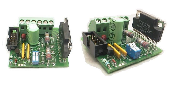
The SLAm Stepper, based on the Allegro SLA7062M, is a very quick and easy to build, 3 amp 40 volt per phase, chopper, unipolar stepper motor controller. With only 15 components, and a very frendly PCB, you can have your motors spinning quicker with this kit than just about any other.
NOTE: This item has been discontinued and is no longer available. Please see one of our other fine stepper drivers.
Like any chopper type of driver, the SLAm is not as smooth as our other, Linistepper, linear driver kit and you may need to add external, mechanical resonance damping in extreem cases.
| Driver | Maximums |
Motors | Pros | Cons | ||
| Amps | Volts | Power | ||||
| Linistepper | 1 or 2, 3 max | 36 | <75 | 5, 6 or 8 wire Unipolar |
Ultra smooth, quiet, low noise, low mid band resonance, motor stays cool, cheap to repair | Limited power, driver heat |
| SLAm | 2 to 3 | 36 | 108 | 5, 6 or 8 wire Unipolar |
Stable, easy to build, small heatsink, tough | Resonance, motor heat/noise |
| THB6064 | up to 4 | 50 | 200 | 4, 6 or 8 wire Bipolar | Powerful, most motors (4, 6 or 8 wires), small heatsink, very tough | Some resonance, motor heat/noise |
| GeckoDrive.com (listed for compairison only) |
3.5-7 | 50-80 | 175-560 | Bipolar | Freaking magic | Cost $80-$166 per axis. |
The kit includes all the components and a professional double sided PCB with top silkscreen, thru plated holes and lead free construction. (RoHS compliant). You add your power supply, motor, heatsink, and standard step and direction signals from Mach 3, TurboCNC or other CNC software.

This item has been discontinued and is no longer available.
Please see one of our other fine stepper
drivers.
To connect to a PC, try our 4 Axis Board or other PMinMO compatible breakout board
See also:
(first draft; 9th Nov 2009)
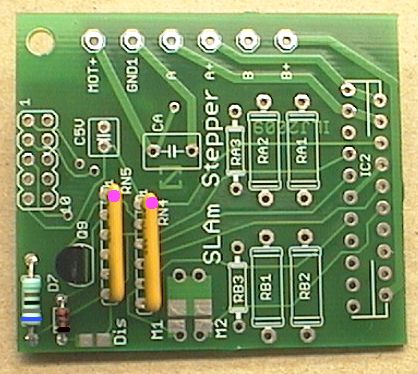
Insert and solder the low-profile parts. (See the PCB overlay diagram above.)
Insert and solder the 68 ohm resistor (R7).
Pre-bend the diode (D7) legs before inserting, its legs must be bent as close as possible to the body of the diode so they fit neatly in the PCB holes.
Pre-bend the legs of the BC327 transistor (Q9) gently with small pointy-nose pliers. Mount the transistor at least 6mm (1/4") above the PCB to reduce strain on its legs.
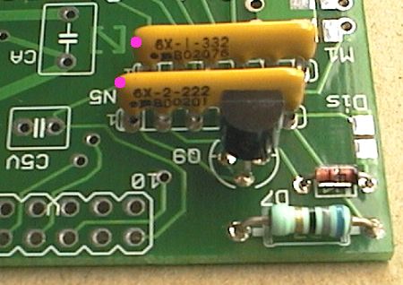
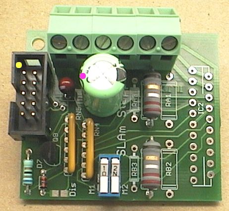
Next insert and solder the 2 YELLOW resistor networks (RN4 and RN5). They must be oriented correctly, see the photos. Pin1 is marked with a BLACK dot on the part, and highlighed with a PINK dot on the photos.
The resistor networks are different values;
(RN4) 3k3 6pin (6X-1-332 yellow)
(RN5) 2k2 6pin (6X-2-222 yellow)
Insert and solder the DIP switch. Orient it so M1=switch1 and M2=switch2 (see the photo).
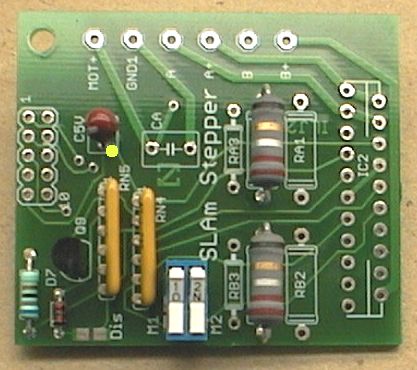
Insert and solder the RED tantalum cap (C5V). Gently scrape its leads to make them shiny and easier to solder (if they are dull). The tantalum MUST be inserted the correct way around. It is marked with a stripe and a little + sign. This is the + lead. It is usually on the right when looking at the writing. The + lead must go on the side marked with the YELLOW dot.
Pre-bend the leads of the current set resistors (RA? and RB?). Mount them about 6mm (1/4") or more above the PCB, this improves cooling and reduces strain on their legs from thermal expansion etc. Space the resistors out, so if you are only using 2 resistors then place them in the middle locations (see photo).
NOTE! The resistors you use for the RA? and RB? section are used to set the
stepper motor current;
(RA1 RB1) 0.47 ohms; current = 0.6 amps (YEL, PUR, SILVER, GOLD, BLACK)
(RA2 RB2) 0.33 ohms; current = 0.9 amps (ORG, ORG, SILVER, GOLD, BLACK)
(RA3 RB3) 0.22 ohms; current = 1.4 amps (RED, RED, SILVER, GOLD, BLACK)
These current values are ADDITIVE. So if you want 2 amps you use the 0.47 ohms pair (0.6 amps) and ADD the 0.22 ohms pair (1.4 amps) to give a total of 2 amps motor current. So there will be 4 resistors soldered in.
Likewise, if you solder in all 6 resistors you get 0.9 + 0.6 + 1.4 which is a total of 2.9 amps.
In the photo above it uses just the pair of 0.22 ohm resistors, so motor current is set at 1.4 amps.
 Step
3 Screwdown Connector / Terminal Block
Step
3 Screwdown Connector / Terminal Block
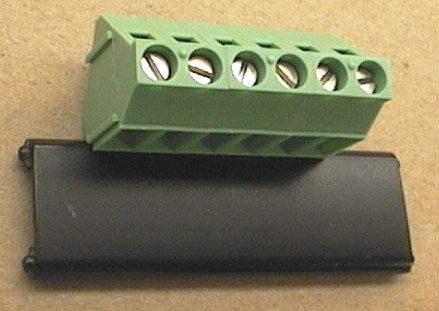
Next assemble the (green) screwdown connector. This comes in 3 parts.
It is important to slide these 3 parts together in exactly the right way. They have 2 tiny "keyways" on each side. You must SLIDE them together correctly!
They are hard to slide (it takes strong fingers!) but they are a quality connector and when joined there is no airgap visible between them, and they lock together solid to make one 6-way connector.
Finally tap them on a piece of plastic (or a plastic ruler) to make sure they are lined up straight.
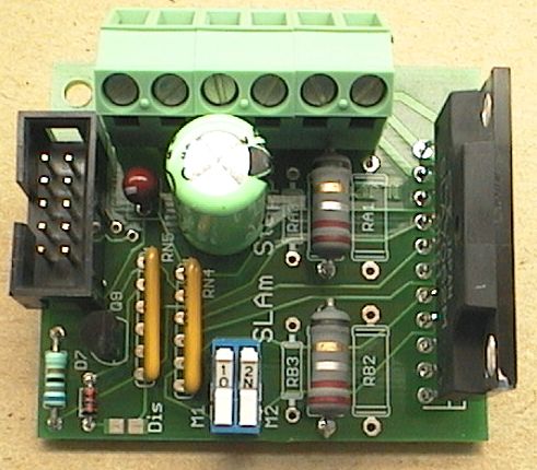
Insert and solder the 6-way screwdown connector. The wire entry holes must be on the outside edge of the PCB; facing up in the photo below. If you install the terminal block connector on the underside of the PCB, still keeping the wire entry holes towards the outside edge, you will be able to read the silkscreened labels on the PCB instead of having to look up where each wire connects. This photo shows the connector on the top of the PCB, where it covers the labels, so that we could show you the direction the wire entry holes must face.
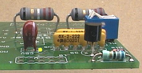
Next do the 470uF electro cap (CA). This must be inserted so it's + pin faces to the left. The other side of the cap is marked with a large black stripe to indicate the - pin.
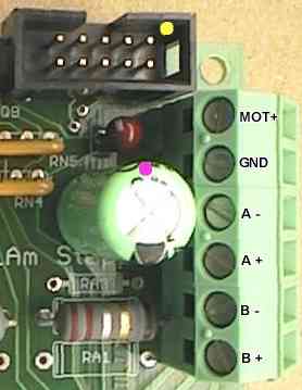
Insert and solder the 10 pin IDC cable connector (black). It is usually soldered as shown in the photo. It's pin 1 is shown marked with a YELLOW dot.
The orientation of this plug relies on the fact that the device you are connecting the OTHER end of the cable to has it's plug oriented correctly. Pin 1 on BOTH ends of the ribbon cable should be the RED wire.
This is an expensive chip and it is difficult to move once soldered in!
So have a think about your heatsink setup before soldering the SLA chip. The SLA chip has its metal body tag internally insulated so it doesn't need any special insulating washers, and it can be screwed directly to a metal heatsink.
Be aware that with the SLA chip soldered in, the PCB extends 2mm (1/12") past the rear mounting surface of the chip. This means your heatsink must be mounted above the PCB (normal), or the heatsink must allow clearance for the PCB in some way (special situation).
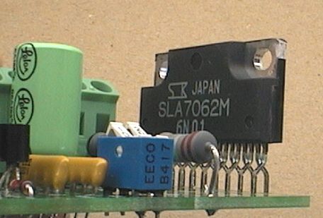
Also the SLA chip should be mounted as high as possible above the PCB, with it's body about 10mm (3/8") above the PCB. There should be only the tips of its legs poking out the bottom of the PCB. This high mounting reduces strain on its legs from thermal expansion, increases airflow around the chip, and gives more clearance to access its mounting screws (see photo below).
Also be aware that the rear legs of the SLA chip extend back to the same plane as its mounting surface, you must make sure these legs cannot touch the metal heatsink!
The SLA7026 only requires a small heatsink for smaller motor currents like 1 amp and a medium sized heatsink for larger motors 2 amps and above.
Larger heatsinks give cooler running of the SLA chip, and reduce the chance of chip failure. So you may want to run a slightly larger heatsink than is necessary, especially if this is to be used for CNC use where it might be operated for hours at a time in a hot cabinet.
Mounting is straightforward. You must apply a small smear of heatsink goop to the rear of the chip (use a tiny flat screwdriver to apply the goop).
Then screw the chip onto the heatsink. You can use 3mm metric bolts and nuts if your heatsink is thin, or if the heatsink is thicker you could use self-tapping 3mm electrical screws into 2.78mm (7/64") interference fit holes drilled directly into the heatsink. The 3mm self-tapping electrical screws can easily be obtained from electronic equipment like video recorders.
First double-check all the part positions and orientations. Especially the capacitors.
Check resistor network RN4, it must be oriented correctly.
Check the soldering on the bottom (and top) of the PCB with a magnifier glass. Make sure there are no shorts. Make sure the solder joints look shiny, curved and complete.
Make sure the optional jumper near the DIP switch (jumper marked 'Dis') is NOT joined.
 NOTE! If
you plug the 10-pin header in reversed, the SLAmStepper will not be harmed
but the 5v regulator on your breakout board (such as the
4 Axis Board or other PMinMO compatible
breakout board) will be shorted and will get VERY HOT. This will be obvious
because the +5v rail will suddenly drop down, close to zero volts. The 5v
regulator on the control board should not be harmed either provided you check
for this and kill the power within a few seconds.
NOTE! If
you plug the 10-pin header in reversed, the SLAmStepper will not be harmed
but the 5v regulator on your breakout board (such as the
4 Axis Board or other PMinMO compatible
breakout board) will be shorted and will get VERY HOT. This will be obvious
because the +5v rail will suddenly drop down, close to zero volts. The 5v
regulator on the control board should not be harmed either provided you check
for this and kill the power within a few seconds.
Now (still with no power) connect a motor by screwing it's wires into the 6-way screwdown terminals. The motor + wire(s) should go into the MOT+ terminal, and the 4 motor phase wires go into A1, A2, B1, B2. (If you don't know your motor wires check the Stepper Motor Wiring page for info on identifying them).
Connect motor power supply (MOT+ and GND1) into the screwdown terminals but don't turn the power on yet. (The MOT+ power wire goes into the same terminal as the motor + lead).
If you are happy that everything is wired correctly and the 10-pin header is plugged in, turn on the power.
The motor should clamp ON and hold in position. At this point your SLAmStepper should be working in low power mode. If step pulses are applied to header pin5 (step) the motor should start turning, be aware that the motor may be turning VERY SLOW depending on the microstep mode.
Check the DIP switch settings, these set the microstep mode;
M1   M2    Mode
off  off   Half-step
off  ON    4th step microstep
ON   off   8th step microstep
ON   ON    16th step microstep
You can change the DIP switches while the motor rotates, it should change the motor speed and smoothness. Be aware that if the motor speed tries to go too fast the motor may stall.
Header pin3 (direction) controls the direction that the motor rotates.
Header pin1 (enable) controls motor current; to move your SLAmStepper
into full power, you must ground this pin.
pin1 +5v = motor at half current (low power "holding" mode) (default)
pin1 0v = motor at full current (run mode)
There is not a lot to troubleshoot on the SLAmStepper because the complex stuff is mainly inside the SLA chip. You can check that the +5v supply is correct, the easiest place to test that is on the bottom of the PCB on the pins of tantalum capacitor C5V. Likewise the main motor power supply voltage can be tested, on the first 2 pins (MOT+ GND1) of the 6 pin screwdown connector.
Most faults come down to incorrect parts placement or orientation or bad soldering. Also check your motor wiring and check the "step" signal (to rotate the motor) is actually being sent from your control board to pin5 of the 10pin header on the SLAmStepper (see the layout diagram at the top of the page).
Here are some common setup faults;
Fault 1. Motor clamps ON but has makes no movement or sound at all.
Cause; No step signal is being received from your control board (common).
Cause; No +5v supply (see the test above).
Fault 2. Motor clamps on but doesn't move at all, and makes a squeal.
Cause; The step signal being sent from your control board is too fast, the
motor can't turn that fast so it stalls.
Cause; Enable line floating high. Connect this pin to ground.
Fault 3. (very common) Motor clamps on ok, but when slow steps are sent the
motor twitches and jerks in the one spot instead of slowly rotating.
Cause; The 4 motor phase wires are connected wrong. The motor is not harmed.
You need to swap 2 motor wires. There is information on the main page about
identifying the motor wires. If you don't know the motor wires, then swap
2 wires; swap the A1 wire with the B1 wire. If that doesn't fix it, swap
the A1 wire with B2. When it is right the motor will start turning. (Turn
off the power before swapping wires!)
Fault 4. Motor turns ok when slow steps are sent, but it turns in the wrong
direction.
Cause; Swap the A1 and A2 wires. The motor will now turn in the opposite
direction. Note! Normally your CNC software will have an option to swap motor
direction but you may want to do it with the wires so all your motors are
the same.
Fault 5. Motor clamps on and may move when not loaded, but has very little
power.
Cause; Enable line floating high. Connect this pin to ground.
Step 9 Disable vs Low Power Hold.
Special note about the optional solder jumper marked 'Dis'.
Normally the "enable" pin (pin1 of 10pin header) selects motor current at full current or half current. This is used so the motor can be put into a low power "holding" mode when it is not being used. Setting the motor to half current means the motor only produces one quarter the heat, but still has significant holding capacity. Most professional machines use this system as the motors can be placed in low power mode during pauses but will not lose their position which can be a problem if they are turned off completely.
However some users prefer the enable pin to provide a complete power-down of the motor. This may be preferable if the motor needs to be manually moved by hand, and in situations where the motor losing position would not matter.
If you want to modify the SLAmStepper so that the enable pin provides complete motor power-down, then you can join the solder jumper marked DIS. After that modification, the enable pin will then power down the motor when connected to +5v (instead of just reducing the motor to half current).
Be aware that in this mode the enable pin requires 5v at 50mA to operate, so a manual switch to +5v will work fine BUT you cannot drive the enable pin directly from a logic source (as you can in the un-modified SLAmStepper) because the logic source will not provide 50mA.
If you need to drive the modified enable pin from a logic source then you need a transistor or a FET to act as a non-inverting buffer to provide greater than 3 volts at around 50mA when the logic pin goes high.
(end)
Questions:
To have full shutdown with logic control could I make these changes?
Replace RN5 with 1100R and RN5C with 680E.
Then when pin1 is high ref voltage would be 0.29v (full power)
and when high ref would be 3v (shut down)
Am I missing something?
James Newton of MassMind replies: Not sure why the changes in resistor value would be required. The current values provide almost total shutdown as it is. But those changes probably won't hurt...
| file: /Techref/io/stepper/SLAm/SLAm_bld.htm, 21KB, , updated: 2016/1/12 22:44, local time: 2025/6/15 14:11,
216.73.216.159,10-2-252-0:LOG IN
|
| ©2025 These pages are served without commercial sponsorship. (No popup ads, etc...).Bandwidth abuse increases hosting cost forcing sponsorship or shutdown. This server aggressively defends against automated copying for any reason including offline viewing, duplication, etc... Please respect this requirement and DO NOT RIP THIS SITE. Questions? <A HREF="http://www.sxlist.com/techref/io/stepper/SLAm/SLAm_bld.htm"> SLAm Stepper Motor Controller, Allegro SLA7062M, Unipolar</A> |
| Did you find what you needed? |
Welcome to sxlist.com!sales, advertizing, & kind contributors just like you! Please don't rip/copy (here's why Copies of the site on CD are available at minimal cost. |
|
The Backwoods Guide to Computer Lingo |
.