The differential amplifier amplifies the difference between two input signals (-) and (+). This amplifier is also referred to as a differential-input single-ended output amplifier. It is a precision voltage difference amplifier, and forms the central basis of more sophisticated instrumentation amplifier circuits.
A differential amplifier is shown in figure 6.18.
The voltage ![]() is given by (cf. voltage divider)
is given by (cf. voltage divider)
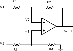
Figure 6.18: Differential amplifier.
![]()
and thus
![]()
leads to
![]()
The differential amplifier is usually limited in its performance by the
low input impedance of ![]() .
Two buffer amplifiers are commonly added to remove this limitation and
form the simple instrumentation amplifier in figure 6.19.
.
Two buffer amplifiers are commonly added to remove this limitation and
form the simple instrumentation amplifier in figure 6.19.
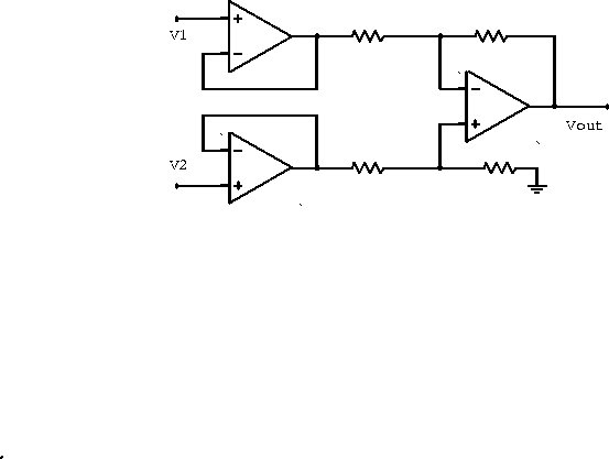
Figure 6.19: Instrumentation amplifier.
Example: If the open-loop gain curve in figure 6.20 describes the amplifier shown, write an expression forwhen
mV.
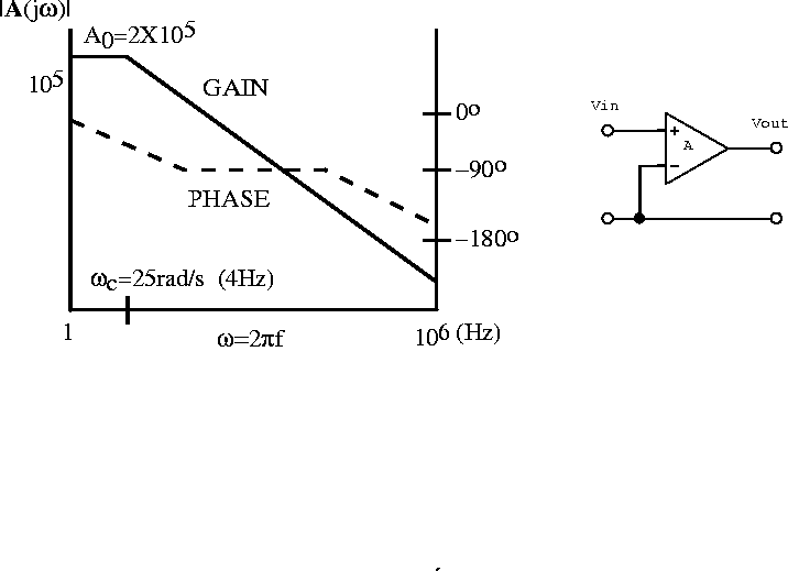
Figure 6.20: Open loop gain curve and amplifier.
By definition

Since
is at ground and
, we have
.

where
and
rad/s (4 Hz).
Since
.
Therefore


and

Example: The variable resistor in the circuit in figure 6.21 provides a DC offset to the output voltage; a circuit of this type is often used to provide a zero output for some specific but nonzero input signal. What range of input voltagecan be zeroed out by this circuit?
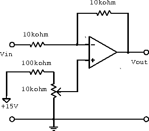
Figure 6.21: Circuit with DC offset.
The current flowing from the input to the output is

Therefore

ranges from 0 to
.
Therefore
ranges from
to
.
For
to
or
V.
The range of input singals that can be zeroed is

Example: A two-input current summing amplifier can be used to shift the DC level of an AC signal. For the circuit shown below, determine the average value of the output signal if the input isV.
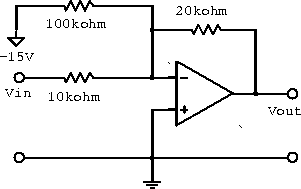
Figure 6.22: Two-input current summing amplifier.
The current sum into the node is

since
is at virtual ground (
).


since
.
Therefore
.
Example: Assuming ideal operational amplifiers, determinefor each of the circuits below. Then determine the single-term approximations to the transfer function at various frequencies, sketch the resulting straight-line approximation to
, and label all magnitudes, corners and slopes.
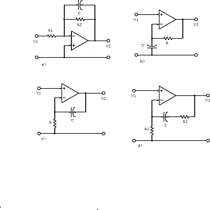
Figure 6.23: Amplifiers with a feedback capacitor.
- a)
- Since
is at virtual ground

where


;
.
;
.
.
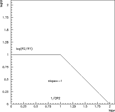
Figure 6.24: Straight-line approximation tofor amplifier a).
- b)

Therefore


;
.
;
.
.
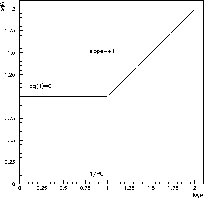
Figure 6.25: Straight-line approximation tofor amplifier b).
- c)

Therefore


;
.
;
.
.
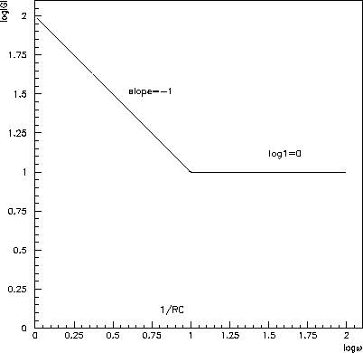
Figure 6.26: Straight-line approximation tofor amplifier c).
- d)

Therefore


;
.
;
.
.
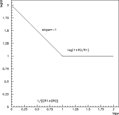
Figure 6.27: Straight-line approximation tofor amplifier d).