A Weekend ICD by Radu Constantinescu
The original Project
M. Adam Davis said:
MPLAB v5.00 is shipped with MPLAB-ICD firmware v2.04 (file MPL876.HEX), targetted for a PIC16F876. You are strongly recommended to upgrade your MPLAB-ICD by replacing the PIC16C73B on the module with a PIC16F876. Upgrading offers the following advantages:
- Support for the PIC16F873/874.
- Improved serial communications.
- The ability to upgrade to future firmware revisions with one mouse click.
So we can program our own 16F876 for the module. All the other parts for the module are in the schematic, and are easily obtained.
pin-out of the RJ-45 connector
after several days of experimenting with my homemade ICD (modified Vpp supply circuit) I came to a painful conclusion - it will not work this way. It will program the chip, but will fail in debug mode. The reason is realy curious - althought there is the Q3 to switch Vpp on and off, MPLAB firmware fiddles with the charge pump on/off _and_ also applies a special condition when the charge pump is switched off and both Q2 and Q3 are opened. There are three or four such pulses 100msec long when the target is being reset. The purpose could be to remove remaining charge from C10-C12. With modified Vpp circuit it of course cannot establish proper signal levels.
R21 was listed as a 100 when I believe it should be 1K. ETN-21 I from MicroChip shows new values for R5, R21 and R22 for operation at Vdd < 4.5V "R21 should be replaced with a 100KOhm and R22 with a 10KOhm resistor. These changes decrease the load on MCLR/Vpp yet maintain the same reference voltage. Replace R5 with a 330 Ohm resistor." This document also has step by step instructions for upgradeing the ICD.
Brian Gregory [briang at cix.co.uk] says:
While I was fitting the changed resistors I also removed the MAX232 and fitted a 16 pin DIL socket for that so I could fit a MAX232A.The MPLAB-ICD seems to communicate with the PC much more reliably with a MAX232A. The reason is possibly because the external capacitors fitted in the MAX232 circuit are only 0.1uF which is okay for the MAX232A but much smaller than the suggested value for the MAX232 (non A) by Maxim.
I would suggest that anyone who's MPLAB-ICD module has a MAX232 rather than a MAX232A consider changing it to a MAX232A. Be careful though - getting the old MAX232 out without damaging the board pushed my soldering skills to the limit. Hint: don't try and get the chip out in one piece - cut all its pins off and remove the pins from the board one by one.
Another possibility would be to change the 0.1uF capacitors C5,C6,C7 & C8 to a higher value - say 1uF tantalum beads. Refer to a MAX232 data sheet for connection polarity.
Replace the charge pump with a +13 volt wall wart, or with a switching power supply like the Burdette switcher to allow other parts to be programmed and to provide margining support.
Note: The LED is used as a reference voltage by the charge pump that creates the 13v signal. This is kind of a poor design, and rumor has it that this will be changed in an ICD II, to be released sometime near this fall.
Advanced engineers might combined a switching power supply with a PIC PWM output controlled regulator to make hardware that can program any PIC or other device! See the CUMP project or Tony Nixons "the Engine" for new firmware to merge with the reverse engineered ICD module firmware for extended abilities.
Now that Octavio Nogueira has (obviously) the ability to write custom firmware for the basic ICD system, there is no reason why he can't add everything listed in the "everything in an '877" idea using the '876 processor and its spare pins (all of port B is unused!) on the ICD module itself.
Howard Cripe [Howard at CRIPE.COM] says:
Thanks to all for your help. I FINALLY figured out what was causing my problems with the ICD. After placing pots in line with the ground leg of the 12v regulator and with the ground leg of the voltage reference LED (aka the power LED), I started adjusting the reference and programming voltages. There is a point where the programming voltage is too high, and that causes the debug functions to stop working. If you lower it to where the debug functions will work, then it won't pass the self test. By adjusting the reference voltage so that it reads VCC a little too high, I can lower the programming voltage to where debugging and the self test work.I guess one good thing to come out of this is that I have two ICD units now, since I decided to start from scratch and try another unit. I need to go back to my first unit and adjust the voltages on it. I'm sure that's all that is wrong with it.
I have a friend here in town that has a Microchip MPLAB-ICD unit. I may borrow it to see what they are expecting for reference & programming voltages, but at least I have a working unit now.
Thanks again and I would be happy to help anyone else out with this project if they need it.
Craig Peacock says:
... I could program and read the device but When I tried to single step it would continuously run the program without stepping or returning control to MPLAB. I would also get the "Can't perform requested operation".My problem was with the voltage level on MCLR. Make sure you have a good Schottky diode for CR2. You can also compensate for a junky diode by reducing R16, the 4K7 Resistor. You should expect around 3.6V on MCLR for normal ICD Operation.
Different Target boards will have different pull up values on MCLR and thus effect the results.
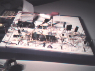
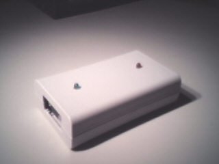
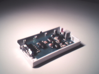
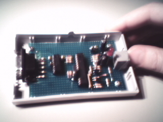
Miroslav Hibler [mhibler at usa.net] has some pictures of his...
I've made my home-brew ICD on experimenting board using '877 (loaded with mpl876.hex) because I had it by hand. I even used resistors and diodes different than specified and on top of it I replaced CR3 diode with LED and it worked the first time I connected the power. I successfully used it to debug some '84 code! Of course, some adjustments to resistor values were necessary to get appropriate voltages but IT WORKED! :) Later I bought '876 and all components originally specified and put all that on a piece of veroboard. Added a plastic box and off I went...
Comments:
Questions:
See:
Code:
Brendan Says:
With help from, Samo, I just finished getting my 'free' ICD working using the Touzet PCB. I ran into two problems. The first was using PN2222A and PN2907A transistors. When I mounted them in the PCB I followed the orientation of Mr. Touzet's implantation layout. It turns out that the pinouts for The PN2222A and PN2907A transistors is reversed. So simply flipping the four transistors solved the first problem.+
The second was programming the F876 used to control the ICD. I didn't follow ETN-21 closely and neglected to check the ID locations and EEprom data check boxes. This caused the ICD to not toggle RC2 to generate the correct VPP voltage. It would still power up and communicate with the PC making me believe it was the circuit that was the problem.
Comments:
Comments:
See also:
http://home.t-online.de/home/520054661375/stolz.de.be/icd/index.html A VERY nice, carefully explained, simple, step-by-step 'build you own' ICD project. Includes details of how to program the PIC without a real programmer.+
Questions:
HI everyone I need your help because please !!! I`ve built my own ICD with the schematics from TOUZET. I`ve followed them step by step, each component, etc. It makes cominication with MPLAB but I`ve had the problem that when I program the PIC 16F877 and finishes show (PASS) but it didn`t do it.+
My circuit only fill the memery locations with 0X0000 `s
I repeat... it`s the same as the TOUZET schematics !!!!
I wonder if you know what could be the possible problem I have, or if you know if there are some extra changes to make to the circuit.
| file: /Techref/piclist/freeicd/index.htm, 16KB, , updated: 2005/11/10 16:17, local time: 2025/5/24 04:12,
owner: RC-yahoo-GA,
216.73.216.22,10-1-137-164:LOG IN
|
| ©2025 These pages are served without commercial sponsorship. (No popup ads, etc...).Bandwidth abuse increases hosting cost forcing sponsorship or shutdown. This server aggressively defends against automated copying for any reason including offline viewing, duplication, etc... Please respect this requirement and DO NOT RIP THIS SITE. Questions? <A HREF="http://www.sxlist.com/techref/piclist/freeicd/index.htm"> Build your own ICD?</A> |
| Did you find what you needed? |
Welcome to sxlist.com!sales, advertizing, & kind contributors just like you! Please don't rip/copy (here's why Copies of the site on CD are available at minimal cost. |
|
The Backwoods Guide to Computer Lingo |
.