You can use the other half of the Radio Shack 276-159B printed circuit board to hold the PIC and components for the 10 included programs.
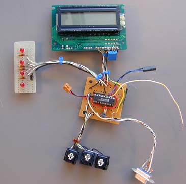
At the left is a small piece of perfboard with 4 LEDs, resistors and a jumper on the ground return line. The size of the resistors depends on the LEDs used. Use 330 ohms or so for normal LEDs, 1500 ohms for low-current LEDs like 276-310 from Radio Shack. The anodes are connected through the resistors to Port B pins RB0 - RB3 with RB0 on the right. Cathodes are connected to ground with a common jumper to disconnect power to the LEDs.
At the bottom are three pushbuttons connected between RB4 - RB6 and ground. I used some pushbuttons salvaged from a computer keyboard which used individual buttons for the keys.
A DB9S connector appears at the lower left. It has a 22K resistor on pin 3 running to RA0. Pin 2 runs to RB7 and pin5 has a wire to ground. Other pins are connected because handshaking is not used.
A two wire connector is provided for a speaker running between RA3 and +4.5 volts. Wires from the piezo speaker are pushed into the connector. One wire has a 100 ohm resistor in series with the speaker.
Power comes into the connector with the red and black wire at the left. I use this as a power switch by pushing in wires from the batteries. I drilled small holes at center left and wrapped thin wire around the power leads as strain relief. You could use a 3 cell battery holder or simply stack the cells in a triangle shape, wrap with electrical tape and solder on wires. Scrape the battery terminals before soldering.
At the top is a $3 LCD display from bgmicro.com. Data lines go to RB0 - RB3. The RS line goes to RA0 and the E line to RA1. The blue square is the contrast pot.
The loose wire on the right goes to RA4 which is used as a pulse counting input. It goes to another small perfboard with a 555 IC on it.
The watch crystal and caps can be seen at the bottom right of the circuit board. It is a good idea to anchor the crystal to the board. All of the components don't have to be attached at the same time of course, only those that are needed for the program you are using. The blue things attached to some wires are cable ties.
Interested:
| file: /Techref/piclist/cheapic/demobd.htm, 3KB, , updated: 2006/1/19 21:08, local time: 2025/5/21 19:00,
216.73.216.184,10-3-150-64:LOG IN
|
| ©2025 These pages are served without commercial sponsorship. (No popup ads, etc...).Bandwidth abuse increases hosting cost forcing sponsorship or shutdown. This server aggressively defends against automated copying for any reason including offline viewing, duplication, etc... Please respect this requirement and DO NOT RIP THIS SITE. Questions? <A HREF="http://www.sxlist.com/techref/piclist/cheapic/demobd.htm"> Demo Board Construction</A> |
| Did you find what you needed? |
Welcome to sxlist.com!sales, advertizing, & kind contributors just like you! Please don't rip/copy (here's why Copies of the site on CD are available at minimal cost. |
|
Ashley Roll has put together a really nice little unit here. Leave off the MAX232 and keep these handy for the few times you need true RS232! |
.