From: http://panteltje.com/panteltje/pic/freq_pic/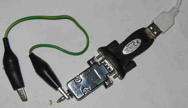
Very nice "Dead Bug" Construction!
;************************************************************************** ; FILE: counter.asm * ; CONTENTS: Simple low-cost digital frequency meter using a PIC 16F628 * ; AUTHOR: Wolfgang Buescher, DL4YHF * ; (based on a work by James Hutchby, MadLab, 1996) * ; REVISIONS: (latest entry first) * ; 2009-08-27 - Added RS232 output option 1200 Bd by Jan Panteltje * ; 2006-05-31 - Added the 'power-save' option which temporarily puts the * ; PIC to sleep (with only the watchdog-oscillator running) * ; 2006-05-15 - New entry in the preconfigured frequency table for 4-MHz * ; IF filters (like "Miss Mosquita" [Moskita] by DK1HE) * ; 2005-08-24 - Cured a bug in the COMMON ANODE decimal point setting . * ; (the "^0xFF" for the AND-mask was missing in macro 'conv') * ; 2005-03-21 - Added a few conditionals to use the same sourcecode * ; to drive a COMMON ANODE display ( DISPLAY_VARIANT_3 ) * ; 2004-03-14 - Fixed a range-switching bug around 8 MHz . * ; - Support TWO different display variants now, * ; optimized for different board layouts, and different clock * ; frequencies (4 MHz for variant 1, 20 MHz for variant 2). * ; 2004-03-05 - Added the feature to add or subtract a frequency offset . * ; 2004-02-18 - Migration to a PIC16F628 with 4 MHz crystal (el Cheapo) * ; - Changed the LED patterns '6' and '9' because they looked * ; like 'b' and 'q' in the old counter version . * ; - Added the auto-ranging feature * ; - Stepped from 24-bit to 32-bit integer arithmetic, to be * ; able to count 50 MHz with 1-second gate time, * ; or (at least) adjust ANY result for the ANY prescaler * ; division ratio, which may give pretty large numbers . * ; - A PIC16F628 worked up to 63 MHz with this firmware . * ;************************************************************************** list P=16F648a ; #include <p16F628.inc> ; processor specific definitions #include <p16f648a.inc> ; processor specific definitions ; Uncomment this if you want RS232 output #define RS232_OUT ; Uncomment the next line if you want pin 8 of the PIC to directly drive a RS232 line (without MAX232 or such). #define NON_INVERTING_RS232_OUT ; BAUD_DIVIDER set to 1 for 9600 Bd, 2 for 4800 Bd, 4 for 2400 Bd, 8 for 1200 Bd, 16 for 600 Bd, 32 for 300 Bd, 64 for 150 Bd, and 128 for 75 Bd. ; Note: for 9600 Bd set BIT_DELAY to 27, or basically a bit lower then for the other baudrates, due to more relative time spend in other instructions. #define BAUD_DIVIDER d'8' ; 1200 Baud ; set baudrate, for small deviations of the internal oscillator this may need to be adapted. #define BIT_DELAY d'165' ; approx 165 for 1200 Bd with 20 MHz clock ; for software RS232 out, NOT using UART #define RS232_PORT PORTB #define RS232_BIT D'2' ; RB2, pin 8 ; print options, all field active looks like: ; 00000050 50 Hz 0.050 kHz ; 19999968 19,999,968 Hz 19.999 MHz ; Uncomment this if you want the first field printed. #define RS232_PRINT_FIELD_1 ; Uncomment this if you want the secind field printed. #define RS232_PRINT_FIELD_2 ; Uncomment this if you want the third field printed. ;#define RS232_PRINT_FIELD_3 ; Note: The first field is for parsing by user space programs. it is recommanded to always leave the field active. ; for unit printing #define KILOHERTZ_FLAG 1 #define NO_INPUT_FLAG 2 #define ZERO_SUPPRESSION_FLAG 4 #define DISPLAY_VARIANT_2 #define DEBUG 0 ; DEBUG=1 for simulation, DEBUG=0 for real hardware ; Selection of LED display control bits... since 2005, three different variants. ; Select ONE OF THESE in MPLAB under "Project".."Build Options".."Macro Definitions"! ; DISP_VARIANT=1 : first prototype, PIC on left side of display ; DISP_VARIANT=2 : second prototype, separated PIC and display board ; DISP_VARIANT=3 : similar as (2), but for COMMON CATHODE display ; Unfortunately it seems impossible to assign a NUMERIC VALUE to a macro ; in MPLAB (not in MPASM!) .... #ifdef DISPLAY_VARIANT_1 #define DISP_VARIANT 1 ; very first (old) prototype by DL4YHF #define COMMON_ANODE 0 #define COMMON_CATHODE 1 #else #ifdef DISPLAY_VARIANT_2 #define DISP_VARIANT 2 ; 5 digits, new layout, COMMON CATHODE #define COMMON_ANODE 0 #define COMMON_CATHODE 1 #else #ifdef DISPLAY_VARIANT_3 ; added 2005-03-21 : #define DISP_VARIANT 3 ; similar as (2), but for COMMON ANODE display #define COMMON_ANODE 1 #define COMMON_CATHODE 0 #else #define DISP_VARIANT 4 #define COMMON_ANODE 0 #define COMMON_CATHODE 1 ; "Error, Must define DISPLAY_VARIANT_1, .._2, or .._3 under project options" ; With MPLAB: Project..Build Options..Project..MPASM..Macro Definitions..Add #endif #endif #endif ;************************************************************************** ; * ; Summary * ; * ;************************************************************************** ; The software functions as a frequency meter with an input signal ; range of 1 Hz to ~ 50 MHz and with an accuracy of +/- 1Hz ; if the oscillator crystal is properly trimmed . ; Signal pulses are counted over a fixed time interval of 1/4 second to ; 1 second (gate time). High frequency pulses are counted over 1/4 s ; to make the meter more responsive with no loss of displayed accuracy. ; Pulses are counted using Timer 0 of the PIC, ; which is set to increment on rising edges on the TMR0 pin. The 8-bit ; hardware register is extended by software into a 32-bit pulse counter. ; If timer 0 rolls over (msb 1 -> 0) between successive polls then the ; high two bytes of the pulse counter are incremented. ; Timer 0 is unable to count more than one pulse per instruction cycle ; (per 4 clock cycles) so the prescaler is used at frequencies above ; 1MHz (4MHz clock / 4) and also to ensure that pulses are not lost ; between polls of timer 0 (which would happen if more than 128 pulses were ; received). Fortunately the prescaler is an asynchronous counter ; which works up to a few ten MHz (sometimes as far as 60 MHz) . ; Timing is based on a software loop of known execution period . The loop ; time is 50 or 20 us which gives integer counts to time 1 s and 1/4 s . ; During this timing loop, the multiplexed LED display is updated . ; The frequency in binary is converted to decimal using a powers-of-ten ; lookup table. The binary powers of ten are repeatedly subtracted from ; the frequency to determine the individual decimal digits. The decimal ; digits are stored at the 8 bytes at 'digits'. Leading zeroes are then ; suppressed and the 4 (or 5) significant digits are converted to LED data ; for the 7-segment displays using a lookup table. ; The signal frequency is displayed on four (or five) 7-segment displays. ; The displays are multiplexed which means that only one display is enabled ; at any one time. The variable 'disp_index' contains the index of the currently ; enabled display. Each display is enabled in turn at a sufficient frequency ; that no flicker is discernable. A prescaler ('disp_timer') is used ; to set the multiplexing frequency to a few hundred Hz. ; The display shows the signal frequency in KHz or MHz, according to the ; following table: ; -------------------------- ; | Frequency | Display | ; -------------------------- ; | < 1Hz | 0 | ; | 1Hz | 0.001[0] | Note: kHz-dot is flashing (blinking) ; | 10Hz | 0.010[0] | ; | 100Hz | 0.100[0] | ; | 1.000KHz | 1.000[0] | ; | 10.00KHz | 10.00[0] | ; | 100.0KHz | 100.0[0] | ; | 1.000MHz | 1.000[0] | Note: MHz-dot is steady (not blinking) ; | 10.00MHz | 10.00[0] | ; -------------------------- ; If there is no signal at all, a single zero is displayed in the 4th(!) digit. ; Overflows are not displayed because they cannot be detected ! ;************************************************************************** ; * ; PIC config definitions * ; * ;************************************************************************** ; '__CONFIG' directive is used to embed configuration data within .asm file. ; The lables following the directive are located in the respective .inc file. ; See respective data sheet for additional information on configuration word. ; Since 2006-05-28, the watchdog must be ENABLE in the config word ; because of its wakeup-from-sleep function (see 'Sleep100ms') . ; EX(16F84:) __CONFIG _CP_OFF & _WDT_ON & _PWRTE_ON & _RC_OSC #if (DISP_VARIANT==1) ; display variant 1 : clocked with 4 MHz (low power, "XT" ) __CONFIG _CP_OFF & _WDT_ON & _PWRTE_ON & _XT_OSC & _LVP_OFF & _BODEN_OFF & _MCLRE_OFF #else ; display variants 2+3 : clocked with 20 MHz (needs "HS" oscillator) __CONFIG _CP_OFF & _WDT_ON & _PWRTE_ON & _HS_OSC & _LVP_OFF & _BODEN_OFF & _MCLRE_OFF #endif ; '__IDLOCS' directive may be used to set the 4 * 4(?!?) ID Location Bits . ; These shall be placed in the HEX file at addresses 0x2000...0x2003 . __IDLOCS H'1234' ; (definitions of "file" registers removed. They are defined in a header file!) ;************************************************************************** ; * ; Port assignments * ; * ;************************************************************************** PORT_A_IO equ b'0000' ; port A I/O mode (all output) PORT_B_IO equ b'00000000' ; port B I/O mode (all output) LEDS_PORT equ PORTB ; 7-segment LEDs port ENABLE_PORT equ PORTA ; display enable port ; Bitmasks to control the digit outputs have been moved to enable_table . ; YHF: Note that 'display #0' is the MOST SIGNIFICANT digit ! #define IOP_PROG_MODE PORTA,5 ; digital input signal, LOW enters programming mode ;************************************************************************** ; * ; Constants and timings * ; * ;************************************************************************** ; processor clock frequency in Hz (4MHz) #if (DISP_VARIANT==1) ; display variant 1 : clocked with 4 MHz (low power consumption) CLOCK equ .4000000 #else ; display variants 2+3 : clocked with 20 MHz (higher resolution) CLOCK equ .20000000 #endif ; microseconds per timing loop #if (DISP_VARIANT==1) ; display variant 1 : clocked with 4 MHz ; 20 microseconds is impossible with 4-MHz-Crystal, so use 50 us instead ! ; Make sure all gate times can be divided by this interval without remainder : ; 1 second / 50 us = 20000 (ok) ; 1/4 second / 50 us = 5000 (ok) ; 1/8 second / 50 us = 2500 (ok) TIME equ .50 #else ; display variants 2+3 : clocked with 20 MHz ; 20 microseconds is impossible with 4-MHz-Crystal, so use 50 us instead ! ; Make sure all gate times can be divided by this interval without remainder : ; 1 second / 20 us = 50000 (ok) ; 1/4 second / 20 us = 12500 (ok) ; 1/8 second / 50 us = 6250 (ok) TIME equ .20 #endif ; variant 1 or 2+3 ? ; Clock cycles per timing loop. See subroutine count_pulses . ; Usually CYCLES=200 (for 4 MHz crystal, 50 usec - loop) ; or 400 (for 20 MHz crystal, 20 usec - loop) CYCLES equ TIME*CLOCK/.1000000 GATE_TIME_LOOPS equ CLOCK/CYCLES ; number of gate-time loops for ONE SECOND gate time LAMPTEST_LOOPS equ CLOCK/(.2*CYCLES) ; number of loops for a 0.5 SECOND lamp test after power-on PROGMODE_LOOPS equ CLOCK/(.10*CYCLES) ; number of delay loops for display in PROGRAMMING MODE (0.1 sec) ; Configuration of power-saving mode : #if( DEBUG ) PSAVE_DELAY_TIME equ .10 ; number of 0.25-sec-intervals before turning off (shorter for debugging) #else PSAVE_DELAY_TIME equ .60 ; number of 0.25-sec-intervals before turning off (some dozen seconds) #endif PSAVE_FLASHUP_TIME equ .14 ; number of 0.7(!)-second-intervals between two flashes in power-saving mode PSAVE_MAX_DIFF equ .10 ; maximum frequency difference (range-dependent, see below) ; Unit: N times "frequency-resolution", see frequency-range table . ; Example: PSAVE_MAX_DIFF=10 means 10*4Hz in Range 1 (1..3.4 MHz) . ; Menu Indices ... must match the jump table PMDisplay + PMExecute ! MI_QUIT equ 0 ; exit from menu MI_PSAVE equ 1 ; turn "power save"-option on and off MI_ADD equ 2 ; save frequency offset to ADD it from now on MI_SUB equ 3 ; save frequency offset to SUBTRACT it from now on MI_ZERO equ 4 ; set the frequency offset to ZERO and leave menu MI_STD_IF equ 5 ; jump into the STANDARD INTERMEDIATE FREQUENCY table.. MI_INDEX_MAX equ 5 ; normal menu indices up to MI_INDEX_MAX . MI_IF_1 equ 6 ; show the 1st standard IF MI_IF_2 equ 7 ; show the 2nd standard IF MI_IF_3 equ 8 ; show the 3rd standard IF MI_IF_4 equ 9 ; show the 4th standard IF MI_IF_5 equ 0x0A ; show the 4th standard IF MI_IF_QT equ 0x0B ; exit standard IF menu without changing anything MI_IF_SUBMENU_MAX equ 0x0A ;************************************************************************** ; * ; File register usage * ; * ;************************************************************************** ; RAM memory (general purpose registers, unfortunately not the same for PIC16F84 & PIC16F628) ; in PIC16F628: RAM from 0x20..0x7F (96 bytes, 0x20.. only accessable in Bank0) ; 0xA0..0xEF (another 80 bytes in Bank1) ; 0x120..0x14F (another 48 bytes in Bank2) ; 0x0F0..0x0FF, 0x170..0x17F , 0x1F0..0x1FF are mapped to 0x70..0x7F (same in all banks) ; So use 0x70..0x7F for context saving in the PIC16F628 and forget 0x0F0.. 0xNNN ! ; ; Note on the 32-bit integer arithmetics as used in this code: ; - They begin with MOST SIGNIFICANT BYTE in memory, but... ; - Every byte location has its own label here, which makes debugging ; with Microchip's simulator much easier (point the mouse on the name ; of a variable to see what I mean !) ; tens_index equ 0x27 ; index into the powers-of-ten table divi equ 0x28 ; power of ten (32 bits) divi_hi equ 0x28 ; same as 'divi' : HIGH byte divi_mh equ 0x29 ; MEDIUM HIGH byte divi_ml equ 0x2A ; MEDIUM LOW byte divi_lo equ 0x2B ; LOW byte timer0_old equ 0x2C ; previous reading from timer0 register gatecnt_hi equ 0x2D ; 16-bit counter (msb first) gatecnt_lo equ 0x2E ; 16-bit counter (lsb last) bTemp equ 0x2F ; temporary 8-bit register, ; may be overwritten in ALL subroutines freq equ 0x30 ; frequency in binary (32 bits).... freq_hi equ 0x30 ; same location, begins with HIGH byte freq_mh equ 0x31 ; ... medium high byte freq_ml equ 0x32 ; ... medium low byte freq_lo equ 0x33 ; ... low byte freq2 equ 0x34 ; frequency too, copied for programming mode freq2_hi equ 0x34 ; same location, begins with HIGH byte freq2_mh equ 0x35 ; ... medium high byte freq2_ml equ 0x36 ; ... medium low byte freq2_lo equ 0x37 ; ... low byte foffs equ 0x38 ; frequency too, copied for programming mode foffs_hi equ 0x38 ; same location, begins with HIGH byte foffs_mh equ 0x39 ; ... medium high byte foffs_ml equ 0x3A ; ... medium low byte foffs_lo equ 0x3B ; ... low byte menu_index equ 0x3C ; menu item for programming mode menu_timer equ 0x3D ; used to detect how long a key was pressed digits equ 0x40 ; frequency as decimal digits (8 bytes)... digit_0 equ 0x40 ; same location as MOST SIGNIFICANT digit, 10-MHz digit_1 equ 0x41 ; usually the 1-MHz-digit digit_2 equ 0x42 ; usually the 100-kHz-digit digit_3 equ 0x43 ; usually the 10-kHz-digit digit_4 equ 0x44 ; usually the 1-kHz-digit digit_5 equ 0x45 ; usually the 100-Hz-digit digit_6 equ 0x46 ; usually the 10-Hz-digit digit_7 equ 0x47 ; usually the 1-Hz-digit digit_8 equ 0x48 ; must contain a blank character (or trailing zero) display0 equ 0x49 ; display #0 data display1 equ 0x4A ; display #1 data display2 equ 0x4B ; display #2 data display3 equ 0x4C ; display #3 data display4 equ 0x4D ; display #4 data disp_index equ 0x4E ; index of the enabled display (0 to 4 for 5-digit display) disp_timer equ 0x4F ; display multiplex timer (5 bits) adjust_shifts equ 0x50 ; count of 'left shifts' to compensate prescaler+gate time blinker equ 0x51 ; prescaler for the flashing 1-kHz-dot psave_timer equ 0x52 ; timer for power-save mode (incremented every 0.25 seconds) psave_freq_lo equ 0x53 ; low-byte of frequency to detect changes for power-save mode psave_flags equ 0x54 ; power-saving flags with the following bits: #define PSFLAG_ACTIVE psave_flags,0 ; clear:normal mode, set:power-saving in action (display blanked) options equ 0x55 ; display options with the following flag-bits: #define OPT_PWRSAVE options,0 ; clear:normal mode, set:power-saving mode enabled tx_reg equ 0x56 bit_count equ 0x57 baud_divider equ 0x58 delay_counter equ 0x59 print_flags equ 0x5A temp equ 0x5B ;************************************************************************** ; * ; Macros (1) * ; * ;************************************************************************** eep_dw macro value ; a DOUBLEWORD split into 4 bytes in the PIC's DATA EEPROM de (value>>.24), (value>>.16)&0xFF, (value>>8)&0xFF, value&0xFF endm ;************************************************************************** ; * ; EEPROM memory definitions * ; * ;************************************************************************** ; for PIC16F84: 0x00..0x3F were valid EEPROM locations (64 byte) ; for PIC16F628: 0x00..0x7F are valid EEPROM locations (128 byte) #define EEPROM_ADR_FREQ_OFFSET 0x00 ; EEPROM location for frequency offset #define EEPROM_ADR_STD_IF_TABLE 0x04 ; EEPROM location for standard IF table (4*4 byte) #define EEPROM_ADR_OPTIONS 0x20 ; EEPROM location for "options" (flags) ; This gives warnings with gpasm 'Warning [220] Address exceeds maximum range for this processor.' ; Initial contents of DATA EEPROM: org (0x2100+EEPROM_ADR_FREQ_OFFSET) eep_dw .0 ; [00..03] initial frequency offset = ZERO org (0x2100+EEPROM_ADR_STD_IF_TABLE) ; standard IF table ... eep_dw .455000 ; [04..07] frequently used in old AM radios eep_dw .3999000 ; [08..0B] used in "Miss Mosquita" (DK1HE / DL QRP AG) eep_dw .4194304 ; [0C..0F] used in other homebrew amateur radio receivers eep_dw .4433619 ; [10..13] sometimes used in homebrew amateur radio receivers eep_dw .10700000 ; [14..17] frequently used in old FM radios ; [18..1F] reserved for other "preprogrammed" values org (0x2100+EEPROM_ADR_OPTIONS) de .0 ; [20] "options" (flags), cleared by default ;************************************************************************** ; * ; More Macros * ; * ;************************************************************************** ;-------------------------------------------------------------------------- ; macros to implement lookup tables - these macros hide the PIC syntax ; used and make the source code more readable ; (YHF: CAUTION - BUT THESE MACROS HIDE SOME VERY NASTY PITFALLS . ; TABLE MUST NOT CROSS PAGE BORDER DUE TO 'ADDWF PCL, f' ! ) ;-------------------------------------------------------------------------- cquad macro value retlw value>>.24 ; high byte retlw (value>>.16)&0xFF ; middle-high byte retlw (value>>8)&0xFF ; middle-low byte retlw value&0xFF ; low byte endm table macro label ; define lookup table label addwf PCL,f ; caution: this is 'PCL' only, cannot add to the full 'PC' in a PIC ! endm ;-------------------------------------------------------------------------- ; add with carry - adds the w register and the carry flag to the file ; register reg, returns the result in <reg> with the carry flag set if overflow ;-------------------------------------------------------------------------- addcwf macro reg local add1,add2 bnc add1 ; branch if no carry set addwf reg , f ; add byte incf reg , f ; add carry skpnz setc goto add2 add1 addwf reg,f ; add byte add2 endm ;-------------------------------------------------------------------------- ; subtract with "no-carry" - subtracts the w register and the no-carry flag ; from the file register reg, returns the result in reg with the no carry flag ; set if underflow ;-------------------------------------------------------------------------- subncwf macro reg local sub1,sub2 bc sub1 ; branch if carry set subwf reg, f ; subtract byte skpnz ; subtract no carry clrc decf reg , f goto sub2 sub1 subwf reg , f ; subtract byte sub2 endm ;-------------------------------------------------------------------------- ; MACRO to perform 32-bit addition - adds the four bytes at op2 to the ; three bytes at op1 (most significant bytes first), returns the result in ; op1 with op2 unchanged and the carry flag set if overflow ;-------------------------------------------------------------------------- add32 macro op1,op2 ; op1 := op1 + op2 movfw op2+3 ; add low byte (bits 7...0) addwf op1+3,f movfw op2+2 ; add middle-low byte (bits 15..8) addcwf op1+2 movfw op2+1 ; add middle-high byte (bits 23...16) addcwf op1+1 movfw op2+0 ; add high byte (bits 31...24) addcwf op1+0 endm ;-------------------------------------------------------------------------- ; MACRO to perform 32-bit subtraction - subtracts the four bytes at op2 ; from the four bytes at op1 (most significant bytes first), returns the ; result in op1 with op2 unchanged and the no carry flag set if underflow ;-------------------------------------------------------------------------- sub32 macro op1,op2 ; op1 := op1 - op2 movfw op2+3 ; subtract low byte subwf op1+3 , f movfw op2+2 ; subtract middle low byte subncwf op1+2 movfw op2+1 ; subtract middle high byte subncwf op1+1 movfw op2+0 ; subtract high byte subncwf op1+0 endm ;-------------------------------------------------------------------------- ; MACRO to negate a 32-bit value ( op := 0 - op ) . ;-------------------------------------------------------------------------- neg32 macro op ; op1 := 0 - op2 local neg_done comf op, f ; invert all 8 bits in high byte comf op+1, f ; invert all 8 bits in middle high byte comf op+2, f ; invert all 8 bits in middle low byte comf op+3, f ; invert all 8 bits in low byte ; Note at this point 0x000000 would have turned into 0xFFFFFFF . ; Must add ONE to complete the TWO's COMPLIMENT calculation ( -0 = 0 ). ; Note that "incf" affects only the Z flag but not the C flag . incfsz op+3, f ; increment low byte (bits 7...0) goto neg_done ; if incremented result NOT zero, we're through ! incfsz op+2, f ; increment middle low byte (bits 15...8) goto neg_done ; if incremented result NOT zero, ... incfsz op+1, f ; increment middle high byte (bits 23...16) goto neg_done ; if ... incfsz op+0, f ; increment high byte (bits 31...24) goto neg_done ; neg_done endm ;********************************************************************** ORG 0x000 ; processor reset vector goto MainInit ; go to beginning of program ; (begin of ROM is too precious to waste for ordinary code, see below...) ;************************************************************************** ; * ; Lookup tables * ; Must be at the start of the code memory to avoid crossing pages !! * ; * ;************************************************************************** ;-------------------------------------------------------------------------- ; 7-segment LED data table ;-------------------------------------------------------------------------- ; Index 0..9 used for decimal numbers, all other indices defined below : CHAR_A equ .10 ; Letters A..F = HEX digits, index 10..15 CHAR_b equ .11 ; CHAR_c equ .12 ; CHAR_d equ .13 ; CHAR_E equ .14 ; CHAR_F equ .15 ; CHAR_G equ .16 ; Other letters used in "programming" mode CHAR_H equ .17 ; CHAR_i equ .18 ; BLANK equ .19 ; blank display TEST equ .20 ; power-on display test CHAR_P equ .21 ; A few other letters for programming mode... CHAR_r equ .22 ; CHAR_o equ .23 ; "Prog" CHAR_Q equ .24 ; "Quit" CHAR_u equ .25 ; CHAR_t equ .26 ; CHAR_S equ .27 ; "Sub" CHAR_Z equ .28 ; "ZEro" CHAR_I equ .29 ; large "I" (left aligned!) for "IF" CHAR_J equ .30 ; CHAR_k equ .31 ; CHAR_L equ .32 ; CHAR_N equ .33 ; CHAR_V equ .34 ; CHAR_EQ equ .35 ; "=" #if (DISP_VARIANT==1) DPPOINT_BIT equ 4 ; decimal point bit (same for all digits) #define _A 0x01 ; bitmask for segment A , etc .. #define _B 0x02 #define _C 0x20 #define _D 0x08 #define _E 0x04 #define _F 0x40 #define _G 0x80 #define _DP 0x10 #endif ; DISPLAY VARIANT #1 #if (DISP_VARIANT==2) || (DISP_VARIANT==3) DPPOINT_BIT equ 1 ; decimal point bit (same for all digits) #define _A 0x40 ; bitmask for segment A , etc .. #define _B 0x80 #define _C 0x04 #define _D 0x01 #define _E 0x08 #define _F 0x10 #define _G 0x20 #define _DP 0x02 #endif ; DISPLAY VARIANT #2 + #3 BLANK_PATTERN equ b'00000000' ; blank display pattern (7-segment code) ;----------------------------------------------------------------------------- ; Table to convert a decimal digit or a special character into 7-segment-code ; Note: In DL4YHF's PIC counter, all digits have the same segment connections, ; so we do not need individual conversion tables for all segments. ; ; AAAA ; F B ; F B ; GGGG ; E C ; E C ; DDDD DP ; ;----------------------------------------------------------------------------- Digit2SevenSeg: addwf PCL,f ; caution: this is 'PCL' only, not 'PC'. Beware of page borders. ; A = 0, B = 1, C = 5, D = 3, E = 2, F = 6, G = 7, DP = 4 #if (COMMON_ANODE) #define SSEG_XORMASK 0xFF ; since 2005-03-21 ... never tested by the author ! #else #define SSEG_XORMASK 0x00 ; for COMMON CATHODE: No bitwise EXOR to the pattern #endif retlw (_A+_B+_C+_D+_E+_F )^SSEG_XORMASK ; ABCDEF. = '0' ( # 0 ) retlw ( _B+_C )^SSEG_XORMASK ; .BC.... = '1' ( # 1 ) retlw (_A+_B +_D+_E +_G)^SSEG_XORMASK ; AB.DE.G = '2' ( # 2 ) retlw (_A+_B+_C+_D +_G)^SSEG_XORMASK ; ABCD..G = '3' ( # 3 ) retlw ( _B+_C +_F+_G)^SSEG_XORMASK ; .BC..FG = '4' ( # 4 ) retlw (_A +_C+_D +_F+_G)^SSEG_XORMASK ; A.CD.FG = '5' ( # 5 ) retlw (_A +_C+_D+_E+_F+_G)^SSEG_XORMASK ; A.CDEFG = '6' ( # 6 ) retlw (_A+_B+_C )^SSEG_XORMASK ; ABC.... = '7' ( # 7 ) retlw (_A+_B+_C+_D+_E+_F+_G)^SSEG_XORMASK ; ABCDEFG = '8' ( # 8 ) retlw (_A+_B+_C+_D +_F+_G)^SSEG_XORMASK ; ABCD.FG = '9' ( # 9 ) retlw (_A+_B+_C +_E+_F+_G)^SSEG_XORMASK ; ABC.EFG = 'A' ( # 10 ) retlw ( _C+_D+_E+_F+_G)^SSEG_XORMASK ; ..CDEFG = 'b' ( # 11 ) retlw ( _D+_E +_G)^SSEG_XORMASK ; ...DE.G = 'c' ( # 12 ) retlw ( _B+_C+_D+_E +_G)^SSEG_XORMASK ; .BCDE.G = 'd' ( # 13 ) retlw (_A +_D+_E+_F+_G)^SSEG_XORMASK ; A..DEFG = 'E' ( # 14 ) retlw (_A +_E+_F+_G)^SSEG_XORMASK ; A...EFG = 'F' ( # 15 ) retlw (_A +_C+_D+_E+_F )^SSEG_XORMASK ; A.CDEF. = 'G' ( # 16 ) retlw ( _B+_C +_E+_F+_G)^SSEG_XORMASK ; .BC.EFG = 'H' ( # 17 ) retlw ( _E )^SSEG_XORMASK ; ....E.. = 'i' ( # 18 ) retlw (BLANK_PATTERN )^SSEG_XORMASK ; ....... = ' ' ( # 19 ) retlw (b'11111111' )^SSEG_XORMASK ; all segments on ( # 20 ) ; A few more letters for programming mode : retlw (_A+_B +_E+_F+_G)^SSEG_XORMASK ; AB..EFG = 'P' ( # 21 ) retlw ( _E +_G)^SSEG_XORMASK ; ....E.G = 'r' ( # 22 ) retlw ( _C+_D+_E +_G)^SSEG_XORMASK ; ..CDE.G = 'o' ( # 23 ) retlw (_A+_B+_C +_F+_G)^SSEG_XORMASK ; ABC..FG = 'Q' ( # 24 ) retlw ( _C+_D+_E )^SSEG_XORMASK ; ..CDE.. = 'u' ( # 25 ) retlw ( _D+_E+_F+_G)^SSEG_XORMASK ; ...DEFG = 't' ( # 26 ) retlw (_A +_C+_D +_F+_G)^SSEG_XORMASK ; A.CD.FG = 'S' ( # 27 ) retlw (_A+_B +_D+_E +_G)^SSEG_XORMASK ; AB.DE.G = 'Z' ( # 28 ) retlw ( _E+_F )^SSEG_XORMASK ; ....EF. = 'I' ( # 29 ) retlw ( _B+_C+_D )^SSEG_XORMASK ; .BCD.. = 'J' ( # 30 ) retlw ( _D+_E+_F+_G)^SSEG_XORMASK ; ...DEFG = 'k' ( # 31 ) retlw ( _D+_E+_F )^SSEG_XORMASK ; ...DEF. = 'L' ( # 32 ) retlw (_A+_B+_C +_E+_F )^SSEG_XORMASK ; ABC.EF. = 'N' ( # 33 ) retlw ( _C+_D+_E+_F )^SSEG_XORMASK ; ..CDEF. = 'V' ( # 34 ) retlw ( _D +_G)^SSEG_XORMASK ; ...D..G = '=' ( # 35 ) ;-------------------------------------------------------------------------- ; Table to control which 7-segment display is enabled. Displays are usually ; COMMON CATHODE (variants 1+2) so pulled low to enable. ; For DISP_VARIANT=3 (COMMON ANODE), the digit-driving pattern is inverted. ; Input: W = 0 means the MOST SIGNIFICANT DIGIT (the leftmost one), etc. ; Result: VALUE to be written to ENABLE_PORT to activate the digit ;-------------------------------------------------------------------------- Digit2MuxValue: ; addwf PCL,f ; caution: this is 'PCL' only, not 'PC' ; Note: If the program counter is affected, a command requires to instruction cycles (=8 osc cycles) #if (DISP_VARIANT==1) ; muliplexer values for DISPLAY VARIANT #1 : retlw b'11110111' ; most significant digit is on PA3 (!) retlw b'11111110' ; next less significant dig. on PA0 (!) retlw b'11111011' ; next less significant dig. on PA2 (!) retlw b'11111101' ; 4th (sometimes the last) digit PA1 (!) retlw b'11111111' ; 5th (OPTIONAL) least significant digit = NOT (PA3+PA2+PA1+PA0) #endif ; DISPLAY VARIANT #1 #if (DISP_VARIANT==2) ; muliplexer values for DISPLAY VARIANT #2 (5 digits, COMMON CATHODE) : retlw b'11110111' ; most significant digit is on PA3 (!) retlw b'11111011' ; next less significant dig. on PA2 (!!) retlw b'11111110' ; next less significant dig. on PA0 (!!) retlw b'11111101' ; 4th (sometimes the last) digit PA1 (!) retlw b'11111111' ; 5th (OPTIONAL) least significant digit = NOT (PA3+PA2+PA1+PA0) #endif ; DISPLAY VARIANT #2 #if (DISP_VARIANT==3) ; muliplexer values for DISPLAY VARIANT #3 (5 digits, COMMON ANODE) : ; Unused bits (b7..b4) are left HIGH as above . retlw b'11111000' ; most significant digit is on PA3 (!) retlw b'11110100' ; next less significant dig. on PA2 (!!) retlw b'11110001' ; next less significant dig. on PA0 (!!) retlw b'11110010' ; 4th (sometimes the last) digit PA1 (!) retlw b'11110000' ; 5th (OPTIONAL) least significant digit = NOT (PA3+PA2+PA1+PA0) #endif ; DISPLAY VARIANT #2 ;-------------------------------------------------------------------------- ; Powers-of-ten table (32 bits, most significant byte first) ; Based on an idea by James Hutchby (MadLab, 1996) . ; Modified for 32-bit arithmetic by Wolfgang Buescher (2004). ;-------------------------------------------------------------------------- TensTable addwf PCL,f cquad .10000000 ; 10 million is sufficient for the counter itself cquad .1000000 cquad .100000 cquad .10000 cquad .1000 cquad .100 cquad .10 cquad .1 ;-------------------------------------------------------------------------- ; DISPLAY jump table for programming mode . ; Loads the display-strings like "quit" etc into the display latches. ; Input parameter: menu_index (0 .. MI_INDEX_MAX) ; Output placed in display0..display3 ; ;-------------------------------------------------------------------------- PMDisplay: movfw menu_index ; load menu index into W register addwf PCL, f ; add W to lower part of program counter (computed jump) goto PmDisp_Quit ; show "quit" (quit programming mode) goto PmDisp_PSave; show "PSave"(power-saving mode on/off) goto PmDisp_Add ; show "add " (add frequency offset) goto PmDisp_Sub ; show "sub " (subtract frequency offset) goto PmDisp_Zero ; show "Zero" (set frequency offset to zero) goto PmDisp_StIF ; show "StdIF" (select standard IF from table) goto PmDisp_IF_1 ; show 1st standard IF from table goto PmDisp_IF_2 ; show 2nd standard IF from table goto PmDisp_IF_3 ; show 3rd standard IF from table goto PmDisp_IF_4 ; show 4th standard IF from table goto PmDisp_IF_5 ; show 5th standard IF from table goto PmDisp_Quit ; show "quit" (quit STANDARD IF menu) ; Add more display strings here if needed ! ;-------------------------------------------------------------------------- ; EXECUTION jump table for programming mode . ; Executes the commands "quit", "psave", "add", "sub", "zero", etc. ; Input parameter: menu_index (0 .. MI_INDEX_MAX) ;-------------------------------------------------------------------------- PMExecute: ; Execute the function belonging to menu_index movfw menu_index ; load menu index into W register addwf PCL, f ; add W to lower part of program counter (computed jump) goto PmExec_Quit ; quit programming mode goto PmExec_PSave; turn power-saving mode on/off goto PmExec_Add ; add frequency offset from now on goto PmExec_Sub ; subtract frequency offset from now on goto PmExec_Zero ; set frequency offset to zero goto PmExec_StIF ; switch to "Standard IF selection mode" goto PmExec_SelIF ; select 1st standard IF from table goto PmExec_SelIF ; select 2nd standard IF from table goto PmExec_SelIF ; select 3rd standard IF from table goto PmExec_SelIF ; select 4th standard IF from table goto PmExec_Quit ; quit STANDARD IF menu ; Add more jumps here if needed ! ;************************************************************************** ; * ; Procedures * ; * ;************************************************************************** ;-------------------------------------------------------------------------- ; Configure the prescaler for TIMER 0 in the PIC's OPTION register . ;-------------------------------------------------------------------------- ; Description of the OPTION register, from the PIC16F628 data sheet: ; bit 7: RBPU: PORTB Pull-up Enable bit ; 1 = PORTB pull-ups are disabled ; 0 = PORTB pull-ups are enabled by individual port latch values ; bit 6: INTEDG: Interrupt Edge Select bit ; 1 = Interrupt on rising edge of RB0/INT pin ; 0 = Interrupt on falling edge of RB0/INT pin ; bit 5: T0CS: TMR0 Clock Source Select bit ; 1 = Transition on RA4/T0CKI pin ; 0 = Internal instruction cycle clock (CLKOUT) ; bit 4: T0SE: TMR0 Source Edge Select bit ; 1 = Increment on high-to-low transition on RA4/T0CKI pin ; 0 = Increment on low-to-high transition on RA4/T0CKI pin ; bit 3: PSA: Prescaler Assignment bit ; 1 = Prescaler is assigned to the WDT ; 0 = Prescaler is assigned to the Timer0 module ; bit 2-0: PS2:PS0: Prescaler Rate Select bits, here shown for TMR0 : ; 000 = 1 : 2 ; ... 111 = 1 : 256 ; Note: to count EVERY pulse (1 : 1) with TMR0, the prescaler ; must be assigned to the WATCHDOG TIMER (WDT) ! ; Some examples (for the OPTION register, parameter in W for SetPrescaler): PSC_DIV_BY_2 equ b'00100000' ; let prescaler divide TMR0 by two PSC_DIV_BY_4 equ b'00100001' ; let prescaler divide TMR0 by 4 PSC_DIV_BY_8 equ b'00100010' ; let prescaler divide TMR0 by 8 PSC_DIV_BY_16 equ b'00100011' ; let prescaler divide TMR0 by 16 PSC_DIV_BY_32 equ b'00100100' ; let prescaler divide TMR0 by 32 PSC_DIV_BY_64 equ b'00100101' ; let prescaler divide TMR0 by 64 PSC_DIV_BY_128 equ b'00100110' ; let prescaler divide TMR0 by 128 PSC_DIV_BY_256 equ b'00100111' ; let prescaler divide TMR0 by 256 SetPrescaler: ; copy W into OPTION register, avoid watchdog trouble clrwdt ; recommended by Microchip ("switching prescaler assignment") errorlevel -302 ; Turn off banking message for the next few instructions.. bsf STATUS, RP0 ;! setting RP0 enables access to OPTION reg ; option register is in bank1. i know. thanks for the warning. movwf OPTION_REG ;! ex: "option" command (yucc) bcf STATUS, RP0 ;! clearing RP0 for normal register access errorlevel +302 ; Enable banking message again retlw 0 PrescalerOff: ; turn the prescaler for TMR0 "off" ; (actually done by assigning the prescaler to the watchdog timer) clrwdt ; clear watchdog timer clrf TMR0 ; clear timer 0 AND PRESCALER(!) errorlevel -302 ; Turn off banking message for the next few instructions.. bsf STATUS, RP0 ;! setting RP0 enables access to OPTION reg ; option register is in bank1. i know. thanks for the warning. movlw b'00100111' ;! recommended by Microchip when ;! changing prescaler assignment from TMR0 to WDT movwf OPTION_REG ;! ex: "option" command (yucc) clrwdt ;! clear watchdog again movlw b'00101111' ;! bit 3 set means PS assigned to WDT now movwf OPTION_REG ;! ex: "option" command (yucc) bcf STATUS, RP0 ;! clearing RP0 for normal register access errorlevel +302 ; Enable banking message again retlw 0 ;-------------------------------------------------------------------------- ; Power-saving subroutine: Puts the PIC to sleep for ROUGHLY 100 milliseconds . ; - crystal oscillator turned OFF during this phase ; - only the internal RC-oscillator for the watchdog keeps running ; - expiration of watchdog during sleep does NOT reset the PIC, ; only wakes it up again so normal operation may resume ; - LED display will be off during this time ;-------------------------------------------------------------------------- Sleep150ms: ; go to sleep for approx. 150 milliseconds, and then RETURN (no reset) ; Details on the PIC's watchdog timer (from PIC16F628 datasheet) : ; > The WDT has a nominal timeout period of 18 ms (with ; > no prescaler). The timeout periods vary with temperature, ; > VDD and process variations from part to part (see ; > DC specs). ; > The Watchdog Timer is a free running on-chip RC oscillator which does ; > not require any external components. This RC oscillator is separate ; > from the ER oscillator of the CLKIN pin. That means that the WDT will run, ; > even if the clock on the OSC1 and OSC2 pins of the device has been stopped, ; > for example, by execution of a SLEEP instruction. ; > During normal operation, a WDT timeout generates a device RESET. ; > If the device is in SLEEP mode, a WDT timeout causes the device to wake-up ; > and continue with normal operation. ; > The WDT can be permanently disabled by programming the configuration bit ; > WDTE as clear . ; In other words, to use the watchdog-timer for "temporary sleep" here , ; it must be ENABLED in the configuration word when programming the PIC. ; (because its not possible to turn it on via software if it's not on). ; But once the watchdog timer is ON, it must be FED periodically otherwise ; it will reset the PIC during normal operation ! ; Here (in the frequency counter), the prescaler remains assigned to timer0 ; so the watchdog interval is ~ 18 milliseconds (+/-, RC-oscillator) . ; > The CLRWDT and SLEEP instructions clear the WDT and the postscaler, ; > if assigned to the WDT, and prevent it from timing out and generating ; > a device RESET. The TO bit in the STATUS register will be cleared upon ; > a Watchdog Timer timeout. #if(COMMON_CATHODE) ; display with COMMON CATHODE : movlw 0x00 ; segment drivers LOW to turn off #else ; not COMMON CATHODE but COMMON ANODE: movlw 0xFF ; segment drivers HIGH to turn off #endif #ifndef RS232_OUT movwf LEDS_PORT ; turn LED segments off #else #ifdef NON_INVERTING_RS232_OUT bcf LEDS_PORT, 2 ; RS232 on RB2 to zero #else bsf LEDS_PORT, 2 ; RS232 on RB2 to one #endif ; NON_INVERTING_RS232_OUT #endif ; RS232_OUT ; Note: The global interrupt-enable flag (GIE) is off in this application ! ; To avoid unintended wake-up on 'interrupt' (port level change), ; disable all interrupt-SOURCES: Clear T0IE,INTE,RBIE,PEIE too : clrf INTCON ; disable all interrupts during SLEEP mode clrwdt ; clear watchdog timer clrf TMR0 ; clear timer 0 AND PRESCALER(!) errorlevel -302 ; Turn off banking message for the next few instructions.. bsf STATUS, RP0 ;! setting RP0 enables access to OPTION reg ; option register is in bank1. i know. thanks for the warning. movlw b'00101011' ;! assign PS to WDT; divide by 8 FOR WDT(!) movwf OPTION_REG ;! ex: "option" command (yucc) bcf STATUS, RP0 ;! clearing RP0 for normal register access errorlevel +302 ; Enable banking message again sleep ; sleep for approx 18 ms (one watchdog interval) ; The SLEEP command clears the Watchdog Timer and stops the main oscillator. ; Only the internal watchdog timer keeps running. ; The WDT is is also cleared when the device wakes-up from SLEEP, ; regardless of the source of wake-up, so no need for 'clrwdt' here ! nop ; arrived here, slept for ~ 8 times 18 milliseconds return ; end Sleep150ms ;-------------------------------------------------------------------------- ; Convert a character into LEDs data for the 7-segment displays, fed with ; the character in w. Bit 7 set means 'decimal point AFTER this digit' . ;-------------------------------------------------------------------------- ; WAS print 5 digits with MHz and kHz indication/. conv macro display ; macro for duplicate code movwf display ; save decimal point bit (msb) andlw 7fh ; mask bit #ifndef RS232_OUT call Digit2SevenSeg ; convert digit into 7-segment-code via table btfsc display,7 ; check bit 7 = decimal point ? #if(COMMON_CATHODE) iorlw 1<<DPPOINT_BIT ; include decimal point if bit 7 set (bitwise OR) #else ; not COMMON CATHODE but COMMON ANODE: decimal point must be 'AND'ed to pattern: andlw (1<<DPPOINT_BIT)^0xFF ; include decimal point if bit 7 set (bitwise AND) #endif movwf display ; set display data register #else ; RS232_OUT #ifdef RS232_PRINT_FIELD_3 movwf temp ; save w ; BLANK, displayed as 'C', indicates no input, going to skip printing those. bcf print_flags, NO_INPUT_FLAG ; no jumps in macro movlw BLANK subwf temp, w btfsc STATUS, Z bsf print_flags, NO_INPUT_FLAG ; get back value to print movfw temp ; test if anything other then zero, if so display it btfss print_flags, NO_INPUT_FLAG call tx_digit_in_w ; test for decimal point btfsc display, 7 call tx_dot #endif ; RS232_PRINT_FIELD_3 #endif endm ; 7 segment out conv_char0: ; display digit #0 (leftmost, or MOST SIGNIFICANT digit) conv display0 retlw 0 conv_char1: ; display #1 conv display1 retlw 0 conv_char2: ; display #2 conv display2 retlw 0 conv_char3: ; display #3 conv display3 retlw 0 conv_char4: ; display #4 (rightmost, or LEAST SIGNIFICANT digit, "ones") conv display4 #ifdef RS232_OUT #ifdef RS232_PRINT_FIELD_3 ; print a space movlw ' ' call tx_w ; test if to print kHz or MHz btfsc print_flags, KILOHERTZ_FLAG goto print_kilo ; print 'M' movlw 'M' call tx_w goto print_hertz print_kilo: movlw 'k' call tx_w ; say Hz print_hertz: movlw 'H' call tx_w movlw 'z' call tx_w #endif RS232_PRINT_FIELD_3 ; send a CR LF movlw D'10' call tx_w movlw D'13' call tx_w #endif ; RS232_OUT retlw 0 ; 7 segment out ;-------------------------------------------------------------------------- ; Fill the 5-digit display latch with blank characters ;-------------------------------------------------------------------------- ClearDisplay: movlw BLANK_PATTERN movwf display0 movwf display1 movwf display2 movwf display3 movwf display4 retlw 0 ;-------------------------------------------------------------------------- ; Save a single Byte in the PIC's Data-EEPROM. ; Input parameters: ; INDF = *FSR contains byte to be written (was once EEDATA) ; w contains EEPROM address offset (i.e. "destination index") ; ;-------------------------------------------------------------------------- ; write to EEPROM data memory as explained in the 16F628 data sheet. ; EEDATA and EEADR must have been set before calling this subroutine ; (optimized for the keyer-state-machine). ; CAUTION : What the lousy datasheet DS40300B wont tell you: ; The example given there for the 16F628 is WRONG ! ; All EEPROM regs are in BANK1 for the 16F628. ; In the PIC16F84, some were in BANK0 others in BANK1.. ; In the PIC16F628, things are much different... all EEPROM regs are in BANK1 ! SaveInEEPROM: ; save "INDF" = *FSR in EEPROM[<w>] bcf INTCON, GIE ; disable INTs errorlevel -302 ; Turn off banking message for the next few instructions.. bsf STATUS, RP0 ;!; Bank1 for "EEADR" access, PIC16F628 ONLY (not F84) movwf EEADR ;!; write into EEPROM address register (BANK1 !!) bcf STATUS, RP0 ;!; Bank0 to read "bStorageData" movfw INDF ; ; w := *FSR (read source data from BANK 0) bsf STATUS, RP0 ;!; Bank1 for "EEDATA" access, PIC16F628 ONLY (not F84) movwf EEDATA ;!; EEDATA(in BANK1) := w (BANK1; F628 only, NOT F84 !!!) bsf EECON1, WREN ;!; set WRite ENable bcf INTCON, GIE ;!; Is this REALLY required as in DS40300B Example 13-2 ? movlw 055h ;!; movwf EECON2 ;!; write 55h movlw 0AAh ;!; movwf EECON2 ;!; write AAh bsf EECON1, WR ;!; set WR bit, begin write ; wait until write access to the EEPROM is complete. SaveEW: btfsc EECON1, WR ;!; WR is cleared after completion of write goto SaveEW ;!; WR=1, write access not finished yet ; Arrived here: the EEPROM write is ready bcf EECON1, WREN ;!; disable further WRites bcf STATUS, RP0 ;!; Bank0 for normal access errorlevel +302 ; Enable banking message again ; bsf INTCON, GIE ; enable INTs ? NOT IN THIS APPLICATION ! retlw 0 ; end SaveInEEPROM ;-------------------------------------------------------------------------- ; Read a single Byte from the PIC's Data-EEPROM. ; Input parameters: ; w contains EEPROM address offset (i.e. "source index") ; will *NOT* be modified to simplify block-read . ; FSR points to the memory location where the byte shall be placed. ; ; Result: ; INDF = *FSR returns the read byte ;-------------------------------------------------------------------------- ; Caution: EEDATA and EEADR have been moved from Bank0(16F84) to Bank1(16F628) ; and the example from the datasheet telling you to switch to ; bank0 to access EEDATA is rubbish (DS40300B page 93 example 13-1). EEPROM_ReadByte: ; read ONE byte from the PIC's data EEPROM movwf bTemp ; save W bcf INTCON, GIE ; disable INTs errorlevel -302 ; Turn off banking message for the next few instructions.. bsf STATUS, RP0 ; Bank1 for ***ALL*** EEPROM registers in 16F628 (!) movwf EEADR ;! write into EEPROM address register bsf EECON1, RD ;! set "Read"-Flag for EEPROM ; why is EECON1.RD not cleared in MPLAB-sim ?!? movf EEDATA, w ;! read byte from EEPROM latch bcf STATUS, RP0 ;! normal access to Bank0 errorlevel +302 ; Enable banking message again ; bsf INTCON, GIE ; re-enable interrupts ? NOT IN THIS APPLICATION ! movwf INDF ; place result in *FSR movfw bTemp ; restore W return ; back to caller ; end EEPROM_ReadByte EEPROM_Read4Byte: ; read FOUR bytes from the PIC's data EEPROM. ; Input parameters: ; w contains EEPROM address offset (i.e. "source index") ; will *NOT* be modified to simplify block-read . ; FSR points to the memory location where the byte shall be placed. call EEPROM_ReadByte ; *FSR = EEPROM[w] (usually bits 31..24) addlw 1 ; next source address incf FSR , f ; next destination address call EEPROM_ReadByte ; *FSR = EEPROM[w] (usually bits 23..16) addlw 1 ; next source address incf FSR , f ; next destination address call EEPROM_ReadByte ; *FSR = EEPROM[w] (usually bits 15..8) addlw 1 ; next source address incf FSR , f ; next destination address goto EEPROM_ReadByte ; *FSR = EEPROM[w] (usually bits 7..0) ; end EEPROM_Read4Byte ;-------------------------------------------------------------------------- ; Count pulses, fed with the number of loop iterations for the gate time . ; WHILE counting, the multiplexed LED display is updated . ; Watchdog is fed in this loop ! ; Input: Count of gate-time-loops in 'gatecnt_hi'+'gatecnt_lo' (16 bit). ; Returns: The number of pulses in 'freq' (clock cycles in []) ;-------------------------------------------------------------------------- count_pulses: clrf freq_hi ; clear pulse counter (bits 31..24) clrf freq_mh ; bits 23..16 clrf freq_ml ; bits 16..8 clrf freq_lo ; bits 7..0 clrf timer0_old ; 'old' value of timer0 to detect toggling MSB clrf TMR0 ; timer register (PIC's hardware timer, 8 bit) nop ; 2 instruction cycle delay nop ; after writing to TMR0 (MPLAB-SIM: set breakpoint + clear stopwatch here) ; --------------- start of critial timing loop >>>>>>>>>>>>>>>>>>>>>>>>>>>>>>>>>> ; The following timing loop must take a well-defined time in total per ; iteration, usually 50 (or 20) microseconds, which can be precisely achieved ; with a 4-MHz-crystal (or 20 MHz for variant 2+3) . ; This gives a basic delay for the frequency counter's gate time . ; The frequency at the input of TIMER 0 (not the prescaler) ; can not exceed f_crystal / 4, ; and every HIGH->LOW transition of bit7 in TIMER0 must be polled here. ; This is safe because .. ; Variant 1: With a 4-MHz-crystal, Timer0 can count up to 1 MHz input, ; MSB toggles every (128/1MHz) = 128 us, polled every 50us -> ok. ; Variant 2: With a 20-MHz-crystal, Timer0 can count up to 4 (not 5?!) MHz input, ; MSB toggles every (128/4MHz) = 32 us, polled every 20us -> ok. ; The numbers in square brackets below are the INSTRUCTION NUMBER within the loop. ; (not the count of oscillator cycles for a single command, which is always 4). ; These values can be checked with the "Stopwatch" function in MPLAB-SIM. ; The goal is to let this loop take EXACTLY <TIME> microseconds (50us or 20us). count1 movfw disp_index ; [1] get the current digit number (disp_index = 0..4) call Digit2MuxValue ; [2,3,4,5,6,7] display (6 commands including call+retlw) movwf bTemp ; [8] save the bit pattern for the multiplexer port movlw display0 ; [9] get the LED display data for the current digit... addwf disp_index,w ; [10] add current digit number to address of LED data movwf FSR ; [11] move address into the PIC's poor 'data pointer' #ifndef RS232_OUT movfw INDF ; [12] w := *(FSR) use indirection register to read from table movwf LEDS_PORT ; [13] set the LED segments #else ; leave port B alone, so as not to disturb RS232 software out. nop nop #endif movfw bTemp ; [14] get the mupliplexer pattern (hurry, hurry !) movwf ENABLE_PORT ; [15] set the LED multiplexer incf disp_timer,f ; [16] increment display-multiplex timer btfsc disp_timer,6 ; [17] (6-bit prescaler) incf disp_index,f ; [18] next display if rolled over bcf disp_timer,6 ; [19] limit disp_timer to 6 bits (!) movfw disp_index ; [20] limit display index to 0...4 sublw .4 ; [21] subtract #4 - W register -> C=0(!) if result negative (W>4) btfss STATUS,C ; [22] skip next instruction if C=1 (#4-W >= 0) clrf disp_index ; [23] if C=0 (disp_index>4) then disp_index=0 ; the following fragments of code always take the same number of clock ; cycles to execute, irrespective of whether the skips take place or not . ; Here still in 'count_pulses'. movfw TMR0 ; [24] read least significant byte of movwf freq_lo ; [25] pulse counter (bits 7..0) movlw 1 ; [26] determine if timer 0 has rolled btfss timer0_old,7 ; [27] over (rolled over if msb was clrw ; [28] previously set and now isn't) btfsc freq_lo,7 ; [29] clrw ; [30] addwf freq_ml,f ; [31] increment high bytes of pulse counter skpnc ; [32] if low byte rolled over incf freq_mh,f ; [33] (mh = "medium high byte" of counter) ; NOTE: we are not modifying freq_hi here ! ; Bits 31..24 may be used later when multiplying with some factor ; (2^n) to compensate for the ASYNCHRON PRESCALER ! btfsc freq_mh,7 ; [34] overflow (freq > 7fffffh) ? goto count3 ; [35] branch if yes movfw freq_lo ; [36] save previous value from timer 0 movwf timer0_old ; [37] tstf gatecnt_lo ; [38] check inner gate-time counter, LOW byte skpnz ; [39] only decrement h-byte if l-byte zero decf gatecnt_hi,f ; [40] decrement gate-time counter, HIGH byte decf gatecnt_lo,f ; [41] always decrement gate-time counter, LOW byte #if (DISP_VARIANT==1) ; only 50 instruction cycles per loop in DISPLAY VARIANT 1 (f_xtal=4 MHz, t_loop=50us) ; Got some instruction cycles left ? Insert a few NOPs to bring to total loop time to 50us. clrwdt ; [42] (ex: nop, but since 2006-05-28 the dog must be fed !) nop ; [43] nop ; [44] nop ; [45] ugh, what a waste of precious CPU power ;-) movfw gatecnt_hi ; [46] counter = 0 ? iorwf gatecnt_lo,w ; [47] skpz ; [48] goto count1 ; [49,50] goto always takes TWO instruction cycles #else ; For VARIANTS 2+3 : 100 instruction cycles per loop ; (f_xtal=20 MHz, t_loop=20us, t_instr=4/20MHz=0.2us) ; Some time may be used for a nice software-based PULSE WIDTH MODULATION ; of the display intensity ... or other goodies/gimmicks one fine day ! clrwdt ; [42] (ex: nop, but since 2006-05-28 the dog must be fed !) movlw .12 ; [43] load additional delay loops (X=12, see below) into W WasteT1: addlw 0xFF ; [44, 48, .. ] btfss STATUS, Z ; [45, 49, .. ] eats 4(!) INSTRUCTION CYCLES per loop goto WasteT1 ; [46+47,50+51, .. ] ; Check this with MPLAB-SIM: here, after loop: [43 + 4*X], with X=12: [91] nop ; [91] nop ; [92] nop ; [93] nop ; [94] nop ; [95] movfw gatecnt_hi ; [96] counter = 0 ? iorwf gatecnt_lo,w ; [97] skpz ; [98] goto count1 ; [99,50] goto always takes TWO instruction cycles #endif ; variant 1 or variant 2/3 ? ; <<<<<<<<<<<<<<<<<<<<<<<< end of timing loop ----------------------------- movfw TMR0 ; get final value from timer 0 movwf freq_lo movlw 1 ; determine if timer 0 has rolled btfss timer0_old,7 ; over (rolled over if msb was clrw ; previously set and now isn't) btfsc freq_lo,7 clrw addwf freq_ml,f ; increment high bytes of pulse skpnc ; counter if low byte rolled incf freq_mh,f ; over count3 retlw 0 ; end of routine 'count_pulses'. Result now in freq_lo..freq_hi. #ifdef RS232_OUT tx_dot: movlw '.' call tx_w return ; send_one_char ; the actual RS232 transmission routine, half-duplex, no-flow-control. ; See AN510 for an explanation tx_digit_in_w: addlw '0' ; zero tx_w: banksel 0 ; return ; movlw 'A' movwf tx_reg ; move W (char to send) to TXReg movlw 0x08 movwf bit_count ; send 8 bits ; send start bit #ifdef NON_INVERTING_RS232_OUT bsf RS232_PORT, RS232_BIT #else bcf RS232_PORT, RS232_BIT #endif nop nop nop nop call bit_delay ; send data bits send_next_bit: bcf STATUS, C rrf tx_reg, 1 ; rotate TXReg btfsc STATUS, C goto set_tx clear_tx: nop ; to get equal set/clear times #ifdef NON_INVERTING_RS232_OUT bsf RS232_PORT, RS232_BIT #else bcf RS232_PORT, RS232_BIT #endif goto ready_tx set_tx: #ifdef NON_INVERTING_RS232_OUT bcf RS232_PORT, RS232_BIT #else bsf RS232_PORT, RS232_BIT #endif goto ready_tx ready_tx: call bit_delay decfsz bit_count,1 ; decrement bit counter (8..0) goto send_next_bit ; loop for next data bit nop nop nop nop nop ; send first stop bit #ifdef NON_INVERTING_RS232_OUT bcf RS232_PORT, RS232_BIT #else bsf RS232_PORT, RS232_BIT #endif call bit_delay ; send second stop bit ; call bit_delay return ; This routine is calibrated with BIT_DELAY to 104 us, that makes BAUD_DIVIDER 1 for 9600 Bd, 2 for 4800 Bd, 4 for 2400 Bd, 8 for 1200 Bd, 16 for 600 Bd, 32 for 300 Bd, 64 for 150 Bd, and 128 for 75 Bd. bit_delay: ; prevent watchdog from interrupting serial com clrwdt ; should be called on a regular basis ; Multiply bit delay for lower baudrates. movlw BAUD_DIVIDER movwf baud_divider baud_divider_loop: ; this is the delay of about 104 uS for 9600 Bd movlw BIT_DELAY ; move baud delay constant to W movwf delay_counter ; initialize delay counter us100_delay_loop: decfsz delay_counter ; decrement delay counter goto us100_delay_loop decfsz baud_divider goto baud_divider_loop return #endif ; RS232_OUT ;-------------------------------------------------------------------------- ; Convert *FSR (32 bit) into BCD and show it on the display . ; Input : INDF = *FSR, 32-bit integer. ; Bad side effect : CONTENTS OF <freq> will be lost !! ;-------------------------------------------------------------------------- ShowInt32_FSR ; Convert <*FSR> (32 bit integer) to 8 BCD-digits ... movfw INDF ; W := *FSR , load LOW byte incf FSR , f ; FSR := FSR + 1 movwf freq ; freq.hi := W movfw INDF ; W := *FSR , load MIDDLE LOW byte incf FSR , f ; FSR := FSR + 1 movwf freq+1 ; freq.mh := W movfw INDF ; W := *FSR , load MIDDLE HIGH byte incf FSR , f ; FSR := FSR + 1 movwf freq+2 ; freq.ml := W movfw INDF ; W := *FSR , load HIGH byte incf FSR , f ; FSR := FSR + 1 movwf freq+3 ; freq.lo := W ; continue with CvtAndDisplayFreq ! ;-------------------------------------------------------------------------- ; Convert <freq> into BCD and show it on the display . ; Input : freq, 32-bit integer. CONTENTS OF <freq> will be lost !! ;-------------------------------------------------------------------------- CvtAndDisplayFreq ; Convert <freq>(32 bit integer) to 8 BCD-digits ... clrf tens_index ; initialise the table index movlw digits ; initialise the indirection register movwf FSR ; ( FSR="pointer"; *FSR=INDF) conv1 ; Loop for ALL POWERS OF TEN in the lookup table.. clrwdt ; feed the watchdog (may stay a bit longer) movfw tens_index ; fetch the next power of ten call TensTable ; (32 bits) from the lookup table movwf divi+0 ; and store in divi incf tens_index , f ; this was the HIGH byte movfw tens_index call TensTable movwf divi+1 incf tens_index , f ; this was the MIDDLE-HIGH byte movfw tens_index call TensTable movwf divi+2 incf tens_index , f ; this was the MIDDLE-LOW byte movfw tens_index call TensTable movwf divi+3 incf tens_index , f ; and this was the LOW-byte of a power of ten ; ex: clrf 0 ; clear the decimal digit .. but address ZERO is called 'INDF' these days ! clrf INDF ; *FSR = 0 conv2 ; Loop to repeatedly subtract divi from freq (32-bit subtract) ; until underflow while incrementing the decimal digit. sub32 freq,divi ; freq := freq - divi (with divi = 10 power N) bnc conv3 ; incf INDF , f ; The RESULT will be written back to freq, goto conv2 ; in other words 'freq' will be lost ! conv3 add32 freq,divi ; freq := freq+divi; ready for next digit incf FSR , f ; step to next decimal digit movlw 8*4 ; 8 x 4-byte entries in TensTable subwf tens_index,w bnz conv1 ; loop until end of table ;-------------------------------------------------------------------------- ; displays the frequency in decimal ;-------------------------------------------------------------------------- display_freq: ; Display the decimal digits according to the following rules ; 000000A => "0.00A" ; 00000AB => "0.0AB" ; 0000ABC => "0.ABC" ; 000ABCD => "A.BCD" ; 00ABCDE => "AB.CD" ; 0ABCDEF => "ABC.D" ; ABCDEFG => "ABCD." ; Modified a lot by WoBu to display kHz as well as MHz : ; If the decimal point means kHz, it flashes. ; If it means MHz, it is on permanently. ; 24 bit unsigned integer could count up to 16777216 (16 mio, slightly over 7 digits) ; which was not enough for a 50 MHz counter, so switched to 32-bit arithmetic . ; #ifdef RS232_OUT #ifdef RS232_PRINT_FIELD_1 ; WAS print 8 digits as one field for parsin gby user programs, no leading zero suppression ; print_value simple movlw digits movwf FSR movfw INDF call tx_digit_in_w incf FSR movfw INDF call tx_digit_in_w incf FSR movfw INDF call tx_digit_in_w incf FSR movfw INDF call tx_digit_in_w incf FSR movfw INDF call tx_digit_in_w incf FSR movfw INDF call tx_digit_in_w incf FSR movfw INDF call tx_digit_in_w incf FSR movfw INDF call tx_digit_in_w ; print 2 spaces movlw ' ' call tx_w movlw ' ' call tx_w #endif ; RS232_PRINT_FIELD_1 #ifdef RS232_PRINT_FIELD_2 ; print value in Hz, with leading zero surpression ; print_value: thoudands separated by commas bsf print_flags, ZERO_SUPPRESSION_FLAG movlw digits movwf FSR tstf INDF bz pri_1000000 pri_10000000: bcf print_flags, ZERO_SUPPRESSION_FLAG movfw INDF tstf INDF bz pri_100000 call tx_digit_in_w pri_1000000: incf FSR ; test if zero supression active btfss print_flags, ZERO_SUPPRESSION_FLAG goto pri_a tstf INDF bz pri_100000 pri_a: bcf print_flags, ZERO_SUPPRESSION_FLAG movfw INDF call tx_digit_in_w movlw ',' call tx_w pri_100000: incf FSR btfss print_flags, ZERO_SUPPRESSION_FLAG goto pri_b tstf INDF bz pri_10000 pri_b: bcf print_flags, ZERO_SUPPRESSION_FLAG movfw INDF call tx_digit_in_w pri_10000: incf FSR btfss print_flags, ZERO_SUPPRESSION_FLAG goto pri_c tstf INDF bz pri_1000 pri_c: bcf print_flags, ZERO_SUPPRESSION_FLAG movfw INDF call tx_digit_in_w pri_1000: incf FSR btfss print_flags, ZERO_SUPPRESSION_FLAG goto pri_d tstf INDF bz pri_100 pri_d: bcf print_flags, ZERO_SUPPRESSION_FLAG movfw INDF call tx_digit_in_w movlw ',' call tx_w pri_100: incf FSR btfss print_flags, ZERO_SUPPRESSION_FLAG goto pri_e tstf INDF bz pri_10 pri_e: bcf print_flags, ZERO_SUPPRESSION_FLAG movfw INDF call tx_digit_in_w pri_10: incf FSR btfss print_flags, ZERO_SUPPRESSION_FLAG goto pri_f tstf INDF bz pri_1 pri_f: bcf print_flags, ZERO_SUPPRESSION_FLAG movfw INDF call tx_digit_in_w pri_1: incf FSR movfw INDF call tx_digit_in_w pri_space: ; space movlw ' ' call tx_w ; Hz movlw 'H' call tx_w movlw 'z' call tx_w ; print 2 spaces movlw ' ' call tx_w movlw ' ' call tx_w #endif ; RS232_PRINT_FIELD_2 #endif ; RS232_OUT ; Display routine for frequencies up to "99.99 MHz" (theoretical): ; (do NOT insert the decimal point yet, ; it would disturb the blanking of LEADING zeroes ) movlw digits ; find the first significant digit.. movwf FSR ; .. by stepping over leading zeroes tstf INDF ; INDF = *(FSR) in "C" syntax, FSR points to 'digits' bnz displ_MHz ; 10-MHz-digit non-zero, show frequency in MHz incf FSR , f ; otherwise skip 1st digit (the 10-MHz place) tstf INDF bnz displ_MHz ; 1-MHz-digit non-zero, show frequency in MHz incf FSR , f ; otherwise skip 2nd digit (the 1-MHz place) tstf INDF bnz displ_kHz ; 100-kHz-digit non-zero, show frequency in kHz (XXX.X) incf FSR , f ; otherwise skip 3rd digit (the 100-kHz place) tstf INDF bnz displ_kHz ; 10-kHz-digit non-zero, show frequency in kHz (XX.XX) incf FSR , f ; Otherwise show digits 5,6,7,8 (there are EIGHT digits) ; show all these frequencies with flashing kHz-point (X.XXX) displ_kHz: ; insert a BLINKING POINT to indicate the kilohertz-digit #ifndef RS232_OUT btfsc blinker, 0 ; check the blink flag (bit 0) for the kHz-point #endif ; RS232_OUT ; in RS232_OUT we always have a dot if kHz (non blinking). bsf digit_4, 7 ; set the decimal point indicating the frequency in kHz . bsf print_flags, KILOHERTZ_FLAG goto display displ_MHz: ; insert a BLINKING POINT to indicate the kilohertz-digit bsf digit_1, 7 ; set the decimal point indicating the frequency in MHz . bcf print_flags, KILOHERTZ_FLAG display: ; Show the FIVE digits beginning at INDF = *(FSR) on the LED display... movfw INDF ; convert the four digits to call conv_char0 ; LED display data incf FSR , f ; increment pointer to next digit movfw INDF ; w = *(FSR) call conv_char1 ; second visible digit incf FSR , f movfw INDF call conv_char2 ; third visible digit incf FSR , f movfw INDF call conv_char3 ; fourth visible digit incf FSR , f movfw INDF goto conv_char4 ; convert fifth visible digit AND RETURN ; end of routine "CvtAndDisplayFreq" ;-------------------------------------------------------------------------- ; main entry point ;-------------------------------------------------------------------------- MainInit: #IF 0 ; Test some math macros ? clrf freq2_hi clrf freq2_mh clrf freq2_ml movlw .100 movwf freq2_lo neg32 freq2 ; -100 = 0xFFFFFF9C #ENDIF ; Test ! movlw PORT_A_IO ; initialise port A errorlevel -302 ; Turn off banking message for the next few instructions.. bsf STATUS, RP0 ;! setting RP0 enables access to TRIS regs movwf PORTA ;! looks like PORTA but is in fact TRISA bcf STATUS, RP0 ;! clearing RP0 enables access to PORTs clrf PORTA movlw PORT_B_IO ; initialise port B bsf STATUS, RP0 ;! setting RP0 enables access to TRIS regs movwf PORTB ;! looks like PORTB but is in fact TRISB bcf STATUS, RP0 ;! clearing RP0 enables access to PORTs errorlevel +302 ; Enable banking message again clrf PORTB clrf disp_index ; initialise display index and clrf disp_timer ; display multiplex timer movlw BLANK ; blank character as dummy ... movwf digit_8 ; for the lowest frequency display range movlw TEST ; test all LED segments call conv_char0 movlw TEST call conv_char1 movlw TEST call conv_char2 movlw TEST call conv_char3 movlw TEST call conv_char4 movlw PSC_DIV_BY_256 ; let the prescaler divide by 256 while testing.. call SetPrescaler ; safely write <W> into option register #if(DEBUG==0) ; Do a LAMP TEST for half a second, including all decimal points : movlw (LAMPTEST_LOOPS)>>8 ; high byte for 0.5 second lamp test movwf gatecnt_hi movlw (LAMPTEST_LOOPS)&0ffh ; low byte for 0.5 second lamp test movwf gatecnt_lo call count_pulses ; some delay to show the test pattern #endif ; not DEBUG MainRestart: ; Here we "restart" the counter after exiting from programming mode : clrf psave_timer ; clear timer for power-save mode (no immediate power-down) clrf psave_flags ; clear all power-saving flags (PSFLAG_ACTIVE, etc) movlw foffs ; load destination address for reading from EEPROM... movwf FSR ; ..into the PIC's pointer register movlw EEPROM_ADR_FREQ_OFFSET+0 ; load the EEPROM-internal address offset (=source index) call EEPROM_Read4Byte ; read from EEPROM: foffs..foffs+4 := EEPROM[W] movlw options ; another destination address for reading from EEPROM.. movwf FSR ; movlw EEPROM_ADR_OPTIONS ; load EEPROM-internal offset of "options"-byte call EEPROM_ReadByte ; read single byte from EEPROM: options := EEEPROM[W] #if(DEBUG==1) bsf OPT_PWRSAVE ; enable power-save mode for debugger/simulator #endif ; DEBUG ; Blank the display until 1st measurement is available : call ClearDisplay ;-------------------------------------------------------------------------- ; main loop : Preparation, auto ranging, measurement, conversion, display ;-------------------------------------------------------------------------- MainLoop: ; re-initialise ports ; ex: tris PORTA; tris PORTB errorlevel -302 ; Turn off banking message for the next few instructions.. bsf STATUS, RP0 ;! setting RP0 enables access to TRIS regs movlw PORT_A_IO ;! movwf PORTA ;! looks like PORTA but is in fact TRISA movlw PORT_B_IO ;! movwf PORTB ;! looks like PORTB but is in fact TRISB bcf STATUS, RP0 ;! clearing RP0 enables access to PORTs clrwdt ; configure TMR0... but clear watchdog timer first movlw b'100000' ; value for OPTION reg: edge - low-to-high transition, ; + prescaler assigned to Timer 0, 1:2 bsf STATUS, RP0 ;! setting RP0 enables access to OPTION reg ; option register is in bank1. i know. thanks for the warning. movwf OPTION_REG ;! ex: "option" command (yucc) bcf STATUS, RP0 ;! clearing RP0 for normal register access errorlevel +302 ; Enable banking message again #ifdef BAUDRATE_TEST test1: movlw 'A' call tx_w call bit_delay call bit_delay call bit_delay call bit_delay call bit_delay call bit_delay call bit_delay call bit_delay call bit_delay call bit_delay call bit_delay call bit_delay call bit_delay call bit_delay call bit_delay call bit_delay call bit_delay call bit_delay goto test1 #endif ; BAUDRATE_TEST ; First do a 'range-detection measurement' to find ; a suitable prescaler ratio. Worst-case-estimation: ; 50 MHz at the input of the async TIMER 0 prescaler ; requires a prescaler ratio of 64 because ; the synchron counter in TIMER 0 accepts a maximum ; frequency of f_osc / 4, here: max. 1 MHz. ; The theoretic maximum frequency is 64 MHz then, which ; was almost reached when tested with a PIC 16F628 . ; The range-detection interval is somewhere near 1/30 seconds (see RANGE_DET_LOOPS), ; so frequencies below 30*64 = 1920 Hz are not detectable at this step. RANGE_DET_LOOPS equ CLOCK/(.30*CYCLES) ; number of gate-time loops to detect the MEASURING RANGE ; (which is required to find a good prescaler value) movlw (RANGE_DET_LOOPS)>>8 ; high byte for RANGE DETECTION loop counter movwf gatecnt_hi movlw (RANGE_DET_LOOPS)&0ffh ; low byte for RANGE DETECTION loop counter movwf gatecnt_lo movlw PSC_DIV_BY_64 ; let the prescaler divide by 64 while testing.. call SetPrescaler ; safely write <W> into option register call count_pulses ; count pulses for the range detection interval (1/16 sec) ; The result will be placed in freq_lo,freq_ml,freq_mh,freq_hi (32 bit) ; but the max count at 64 MHz input, 1/30 sec gate time, and prescaler=64 will be : ; 64MHz / (30 * 64) = 33333 pulses, so only 16 bits in the counter ; are required here (call them "testcount", f_in = testcount * 30*64) . ; The frequency resolution of this coarse measurement is 64*16 Hz = roughly 1 kHz. ; (for that reason it's not suited for "wake-up from power-save on frequency-change") #if 0 ; TEST auto ranging movlw (.8500)>>8 ; high byte of counted pulses movwf freq_ml movlw (.8500)&0ffh ; low byte of counted pulses movwf freq_lo #endif ; end TEST ; Load the default (soft-)counters for the GATE TIME. ; Most measuring ranges use a 1/4 second gate time ! movlw (GATE_TIME_LOOPS/4)>>8 ; high byte of gate time movwf gatecnt_hi movlw (GATE_TIME_LOOPS/4)&0ffh ; low byte of gate time movwf gatecnt_lo ; Increment the "blinker" once every 0.25 seconds. ; (if the gate time is longer, flashing will be slower, that's acceptable) incf blinker, f incf psave_timer, f ; increment the power-save timer every 0.25 seconds too (checked somewhere else) ; Look at the range-detection count ("testcount") ; and decide which measuring range to use, beginning with the highest frequency range #if (DISP_VARIANT==1) ; Ranges FOR VARIANT 1, 4 MHz CRYSTAL (low-power variant, less resolution at HF !) ; Rng testcount f_in prescaler gate_time display, resolution ; (1) 0..6 0.. 11.5 kHz 1 1 second X.XXXkHz, 0.001kHz (4 digits only) ; (2) 7..54 ..103.6 kHz 1 1/2 second XX.XXXkHz, 0.002kHz (last digit steps by 2) ; (3) 55..511 ..981.1 kHz 1 1/4 second XXX.XXkHz, 0.004kHz (last digit steps by 1) ; (4) 512..1023 .. 1.9 MHz 2 1/4 second XXX.XXkHz, 0.008kHz (last digit steps by 1) ; (5) 1024..2047 .. 3.9 MHz 4 1/4 second X.XXXXMHz, 0.016kHz (last digit steps by 1) ; (6) 2048..4095 .. 7.9 MHz 8 1/4 second X.XXXXMHz, 0.032kHz (last digit steps by 1) ; (7) 4096..8191 ... 15.7 MHz 16 1/4 second X.XXXXMHz, 0.064kHz (last digit steps by 1) ; (8) 8192..16383 ... 31.4 MHz 32 1/4 second X.XXXXMHz, 0.128kHz (last digit steps by 1 or 2) ; (9) 16384..33300 ... 63.9 MHz 64 1/4 second XX.XXXMHz, 0.256kHz (last digit steps by 1) movfw freq_ml ; first look at bits 15..8 of the 'test count' result andlw b'11000000' ; any of bits 15..14 set (>=16384) -> no Z flag -> range 9 btfss STATUS,Z ; skip next instruction if ZERO-flag set (!) goto Range9 ; far jump to range 9 btfsc freq_ml,5 ; bit 13 set (>=8192) -> range 8 goto Range8 btfsc freq_ml,4 ; bit 12 set (>=4096) -> range 7 goto Range7 btfsc freq_ml,3 ; bit 11 set (>=2048) -> range 6 goto Range6 btfsc freq_ml,2 ; bit 10 set (>=1024) -> range 5 goto Range5 btfsc freq_ml,1 ; bit 9 set (>=512) -> range 4 goto Range4 btfsc freq_ml,0 ; bit 8 set (>=256) -> no Z flag -> range 3 goto Range3 movfw freq_lo ; now look at bits 7..0 only .. sublw .54 ; subtract #54 - W register -> C=0 if result negative btfss STATUS,C ; skip next instruction if C=1 (#54-W >= 0) goto Range3 ; freq > 100kHz -> also range 3 movfw freq_lo ; look at bits 7..0 again .. sublw .5 ; subtract #5 - W register -> C=0 if result negative btfss STATUS,C ; skip next instruction if C=1 goto Range2 ; freq > 10kHz -> range 2 goto Range1 ; otherwise range 1 #endif ; end of specific range-switching for DISPLAY VARIANT #1 #if (DISP_VARIANT==2) || (DISP_VARIANT==3) ; Ranges FOR VARIANT 2+3, 20 MHz CRYSTAL (draws more power, but gives better resolution at HF ) ; Even if PIC clocked with 20MHz, keep the input of TIMER0 below 4(!) MHz . ; Rng testcount f_in prescaler gate_time display, resolution ; (1) 0..6 0.. 11.5 kHz 1 1 second X.XXXkHz, 0.001kHz (4 digits only) ; (2) 7..54 ..103.6 kHz 1 1/2 second XX.XXXkHz, 0.002kHz (last digit steps by 2) ; (3) 44..2047 .. 3.9 MHz 1 1/4 second X.XXXXMHz, 4 Hz (last digit steps by 1) ; (4) 2048..4095 .. 7.9 MHz 2 1/4 second X.XXXXMHz, 8 Hz (last digit steps by 1) ; (5) 4096..8191 ... 15.7 MHz 4 1/4 second X.XXXXMHz, 16 Hz (last digit steps by 1) ; (6) 8192..16383 ... 31.4 MHz 8 1/4 second X.XXXXMHz, 32 Hz (last digit steps by 1 or 2) ; (7) 16384..33330 ... 63.9 MHz 16 1/4 second XX.XXXMHz, 64 Hz (last digit steps by 1) movfw freq_ml ; first look at bits 15..8 of the 'test count' result andlw b'11000000' ; any of bits 15..14 set (>=16384) -> no Z flag -> range 7 btfss STATUS,Z ; skip next instruction if ZERO-flag set (!) goto Range7 ; far jump to range 7 btfsc freq_ml,5 ; bit 13 set (>=8192) -> range 6 goto Range6 btfsc freq_ml,4 ; bit 12 set (>=4096) -> range 5 goto Range5 btfsc freq_ml,3 ; bit 11 set (>=2048) -> range 4 goto Range4 btfsc freq_ml,2 ; bit 10 set (>=1024) -> range 3 goto Range3 btfsc freq_ml,1 ; bit 9 set (>=512) -> range 3 goto Range3 btfsc freq_ml,0 ; bit 8 set (>=256) -> no Z flag -> range 3 goto Range3 movfw freq_lo ; now look at bits 7..0 only .. sublw .54 ; subtract #54 - W register -> C=0 if result negative btfss STATUS,C ; skip next instruction if C=1 (#54-W >= 0) goto Range3 ; freq > 100kHz -> also range 3 movfw freq_lo ; look at bits 7..0 again .. sublw .5 ; subtract #5 - W register -> C=0 if result negative btfss STATUS,C ; skip next instruction if C=1 goto Range2 ; freq > 10kHz -> range 2 goto Range1 ; otherwise range 1 (lowest frequencies) #endif ; end of specific range-switching for DISPLAY VARIANT #2 Range1: ; Range 1: async prescaler off, 1 second gate time for very low frequencies : call PrescalerOff ; turn hardware prescaler off incf psave_timer, f ; increment power-save timer three more times incf psave_timer, f ; (1 sec-gate instead of 0.25) incf psave_timer, f ; Load the GATE TIMER (as count of loops) for this measuring range. movlw (GATE_TIME_LOOPS)>>8 ; high byte for 1 second gate time movwf gatecnt_hi movlw (GATE_TIME_LOOPS)&0ffh ; low byte for 1 second gate time movwf gatecnt_lo ; Load the count of "left shifts" to compensate gate time + prescaler : movlw 0 ; no need to multiply with prescaler 1:1 and 1-sec gate time goto GoMeasure Range2: ; Range 2: async prescaler off, 1/2 second gate time for quite low frequencies : call PrescalerOff ; turn hardware prescaler off incf psave_timer, f ; increment power-save timer one more time (0.5 sec-gate instead of 0.25) ; Load the GATE TIMER (as count of loops) for this measuring range. movlw (GATE_TIME_LOOPS/2)>>8 ; high byte for 1/2 second gate time movwf gatecnt_hi movlw (GATE_TIME_LOOPS/2)&0ffh ; low byte for 1/2 second gate time movwf gatecnt_lo ; Load the count of "left shifts" to compensate gate time + prescaler : movlw 1 ; multiply by 2 (=2^1) later to compensate gate time (1/2 s) goto GoMeasure Range3: ; Range 3: async prescaler off, gate time = default (1/4 sec) : call PrescalerOff ; turn hardware prescaler off movlw 2 ; multiply by 4 (=2^2) later to compensate gate time (1/4 s) goto GoMeasure Range4: ; Range 4: prescaler divide by 2 , gate time = default (1/4 sec) : movlw PSC_DIV_BY_2 ; let the prescaler divide by 2 while MEASURING... call SetPrescaler ; safely write <W> into option register movlw 3 ; multiply by 8 (=2^3) later to compensate prescaling (1:2) * gate time (1/4 s) goto GoMeasure Range5: ; Range 5: prescaler divide by 4 , gate time = default (1/4 sec) : movlw PSC_DIV_BY_4 ; let the prescaler divide by 2 while MEASURING... call SetPrescaler ; safely write <W> into option register movlw 4 ; multiply by 16 (=2^4) later to compensate prescaling (1:4) * gate time (1/4 s) goto GoMeasure Range6: ; Range 6: prescaler divide by 8 , gate time = default (1/4 sec) : movlw PSC_DIV_BY_8 ; let the prescaler divide by 2 while MEASURING... call SetPrescaler ; safely write <W> into option register movlw 5 ; multiply by 32 (=2^5) later to compensate prescaling (1:8) * gate time (1/4 s) goto GoMeasure Range7: ; Range 7: prescaler divide by 16 , gate time = default (1/4 sec) : movlw PSC_DIV_BY_16 ; let the prescaler divide by 2 while MEASURING... call SetPrescaler ; safely write <W> into option register movlw 6 ; multiply by 64 (=2^6) later to compensate prescaling (1:16) * gate time (1/4 s) goto GoMeasure #if (DISP_VARIANT==1) ; Ranges 8 + 9 are only needed for VARIANT 1 with 4-MHz crystal : Range8: ; Range 8: prescaler divide by 32 , gate time = default (1/4 sec) : movlw PSC_DIV_BY_32 ; let the prescaler divide by 2 while MEASURING... call SetPrescaler ; safely write <W> into option register movlw 7 ; multiply by 128 (=2^7) later to compensate prescaling (1:32) * gate time (1/4 s) goto GoMeasure Range9: ; Range 9: prescaler divide by 64 , gate time = default (1/4 sec) : movlw PSC_DIV_BY_64 ; let the prescaler divide by 2 while MEASURING... call SetPrescaler ; safely write <W> into option register movlw 8 ; multiply by 256 (=2^8) later to compensate prescaling (1:64) * gate time (1/4 s) goto GoMeasure #endif ; (DISP_VARIANT==1) GoMeasure: movwf adjust_shifts ; save the number of "arithmetic left shifts" for later call count_pulses ; count pulses for 1, 1/2, or 1/8 s . ; Result in freq_lo,freq_ml,freq_mh,freq_hi (32 bit) now, ; NOT adjusted for the gate-time or prescaler division ratio yet. ;----------------- Power-saving mode ------------------------------------ ; Power-saving mode enabled or about to be activated ? btfss OPT_PWRSAVE ; Power-save mode enabled (from config) ? goto PsNotBlanked ; Arrived here: power-saving is ENABLED through the config, ; but not necessarily ACTIVE at the moment . ; If power-save is already active, clear the display (may have 'flashed up') btfsc PSFLAG_ACTIVE ; if power-save already 'ACTIVE'.. call ClearDisplay ; then clear the display (latch) ; Next: Check if the frequency has changed significantly ; since the last 'reload' of the power-save timer. ; To keep things simple, only look at the LOW BYTES of the ; 'current' and the 'old' frequency reading at this stage ; (BEFORE multiplying the result with two power adjust_shifts) . ; 'psave_freq_lo' is an "old" reading; 'freq_lo' the current frequency. ; Both are UNSIGNED 8-bit values ! movfw freq_lo ; get low-byte of current frequency subwf psave_freq_lo, w ; W := freq_lo - psave_freq_lo ; Make the difference (new minus old frequency in W) positive : movwf bTemp ; bTemp := (freq_lo - psave_freq_lo) btfss bTemp,7 ; check the sign-bit (=MSB) goto PsDiffPos ; difference already posivite, else : comf bTemp,f ; bTemp := ~bTemp (for example, 0xFF -> 0x00) incf bTemp,f ; add one for two's complement PsDiffPos:; Arrived here: difference made positive, i.e. bTemp = abs(freq_lo - psave_freq_lo) . ; If the frequency-difference is 'quite high', ; turn off the flag PSFLAG_ACTIVE and clear the power-save-timer: movfw bTemp ; W := abs(freq_lo - psave_freq_lo) sublw PSAVE_MAX_DIFF ; W := PSAVE_MAX_DIFF - W ; C=0 if result negative (=large f-diff) btfsc STATUS,C ; skip next instruction if large frequency difference goto PsSmallDiff ; PsLargeDiff: ; Arrived here: there's a LARGE difference between 'current' and 'old' frequency bcf PSFLAG_ACTIVE ; Back to normal display mode clrf psave_timer ; restart 'power-save' activation timer (with display ON) movfw freq_lo ; set 'current' frequency as new 'old' frequency... movwf psave_freq_lo ; for the next XX-second interval ! goto PsNotBlanked PsSmallDiff: ; Arrived here: there's only a SMALL difference between 'current' and 'old' frequency . btfsc PSFLAG_ACTIVE ; power-save already 'ACTIVE' ? goto PsActive ; yes, already active -> check for flash-up ; Check the power-save timer; it may be time to turn the display OFF now : movfw psave_timer ; if(psave_timer > PSAVE_DELAY_TIME ) ... sublw PSAVE_DELAY_TIME ; subtract #PSAVE_DELAY_TIME - W -> C=0 if result negative btfsc STATUS,C ; skip next instruction if carry=0 (PSAVE_DELAY_TIME-W < 0) goto PsNoTimeout ; psave_timer still low, no 'timeout' yet ! ; Arrived here: Display was on, but almost no change in frequency -> enter power-saving mode movlw PSAVE_FLASHUP_TIME-1 ; let display flash up once before turning off movwf psave_timer ; ... to avoid overflow when incrementing it later bsf PSFLAG_ACTIVE ; set the flag 'power-save ACTIVE' to blank the display movfw freq_lo ; save low-byte of frequency when ENTERING power-save mode movwf psave_freq_lo goto PsSleep ; sleep for the first 600-millisecond-interval now PsActive: ; Here if power-saving mode already active . ; Check it it's time to let the display flash up for a short time ; to show the operator we're still alive ! movfw psave_timer ; if(psave_timer > PSAVE_DELAY_TIME ) ... sublw PSAVE_FLASHUP_TIME ; subtract #PSAVE_FLASHUP_TIME - W -> C=0 if result negative btfsc STATUS,C ; skip next instruction if (PSAVE_FLASHUP_TIME-psave_timer) < 0 goto PsSleep ; psave_timer still low, don't 'flash up' yet ! PsFlashUp: clrf psave_timer ; prepare timer for next period of darkness movfw freq_lo ; avoid turning the display on .. movwf psave_freq_lo ; .. if the VFO is only "slowly creeping" clrf psave_timer ; restart 'power-save' activation timer (with display OFF) goto PsNotBlanked ; and let the display flash up for one gate interval PsNoTimeout: ; small frequency difference, AND psave_timer still low.. ; Already in "power-save"-mode or normal display ? btfss PSFLAG_ACTIVE ; check the flag 'power-save ACTIVE' goto PsNotBlanked ; not set -> normal display (not blanked) ; Arrived here: 'Saving power', which means the display ; is blanked MOST of the time (but it may flash up every XX seconds ; to show the operator we're still alive) . PsSleep: call Sleep150ms ; put CPU to sleep for ~500 milliseconds.. call Sleep150ms call Sleep150ms goto CheckProgMode ; skip integer->BCD conversion (save power) PsNotBlanked: ; Display is not blanked for power-saving mode at the moment. ; If this 'absolute difference' is quite large, ; clear the power-save timer to prevent turning off the display ; within the next XX seconds : ; Reload the power-save-timer if there was a significant change ; since the last comparison. PrepDisp: ; Prepare the frequency (32-bit 'unadjusted' integer) for display: ; Multiply freq by 2^adjust_shifts to adjust for the prescaling ; WQS 2 frequency in Hz here ; and the timing period . The result will be a frequency in HERTZ, 32-bit integer. ; Note: the adjustment factor may be ONE which means no shift at all. tstf adjust_shifts bz NoAdjust Adjust: clrc rlf freq_lo , f rlf freq_ml , f rlf freq_mh , f rlf freq_hi , f decfsz adjust_shifts, f goto Adjust NoAdjust: ; WAS 3 ; Check the result against under- and overflow. ; (There should be none if the frequency didn't change too rapidly ; between the range-detection and the actual measurement ) movfw freq_hi ; underflow (freq = 0) ? iorwf freq_mh,w iorwf freq_ml,w iorwf freq_lo,w #ifndef RS232_OUT ; WAS this causes print to skip bz freq_underflow ; branch if yes #endif ; ! RS232_OUT btfsc freq_hi,7 ; overflow (freq > 7FFfffffh) ? goto freq_overflow ; branch if yes ; WAS 4 ; freq in freq_hi, freq_mh, freq_ml, freq_lo ???? ; 32 bit binary to BCD, display? ; Save the frequency value without offset for programming mode in 'freq2', ; because 'freq' will be lost when splitting it into digits. movfw freq_hi movwf freq2_hi movfw freq_mh movwf freq2_mh movfw freq_ml movwf freq2_ml movfw freq_lo movwf freq2_lo ; Add the programmable frequency offset ; (often used to add or subtract the intermediate frequency in superhet receivers) add32 freq, foffs ; freq := freq+foffs; 32-bit ; If the result is negative, make it posisive btfss freq_hi, 7 ; bit 7 of the most significant byte is the SIGN goto f_positive ; skip the following MACRO if positive.. neg32 freq ; freq := -freq (32-bit) f_positive: call CvtAndDisplayFreq ; Convert <freq> into BCD and show it on the display CheckProgMode: ; Arrived here, the frequency is still valid in 'freq2' ; but not in 'freq'. Poll the programming key, ; maybe the user wants to save this value as the new ; FREQUENCY OFFSET . #ifdef RS232_OUT ; no prog loop in RS232_OUT, no offset, just a frequency counter. goto MainLoop #endif ; RS232_out #if(DEBUG==0) btfss IOP_PROG_MODE ; Button "program mode" pressed ? goto EnterProgLoop ; Yes, enter programming mode ! #endif ; not DEBUG goto MainLoop ; end of main loop ;-------------------------------------------------------------------------- ; frequency underflow (frequency < 1Hz) ;-------------------------------------------------------------------------- freq_underflow: movlw BLANK ; display underflow as " 0[0]" call conv_char0 movlw BLANK call conv_char1 movlw BLANK call conv_char2 movlw 0 ; why not 'zero' in the last digit ? call conv_char3 movlw BLANK call conv_char4 ; because the 5th digit is OPTIONAL ! goto CheckProgMode ;-------------------------------------------------------------------------- ; frequency overflow (frequency > 50MHz) ;-------------------------------------------------------------------------- freq_overflow: movlw BLANK ; display overflow as " E" call conv_char0 movlw BLANK call conv_char1 movlw BLANK call conv_char2 movlw CHAR_E call conv_char3 movlw BLANK call conv_char4 ; Note that the 5th digit is OPTIONAL ! goto MainLoop ; end of main loop ;-------------------------------------------------------------------------- ; program loop : ; - show a simple menu to select ADD or SUBTRACT offset, ; - save the frequency offset value permanently in DATA EEPROM, ; - return to the main loop when done . ;-------------------------------------------------------------------------- ProgModeDisplay ; Subroutine to update the LED display in programming mode + delay movlw (PROGMODE_LOOPS)>>8 ; high byte for delay loops (usually 0.1 second) movwf gatecnt_hi movlw (PROGMODE_LOOPS)&0ffh ; low byte for delay loops movwf gatecnt_lo goto count_pulses ; update mux display + some delay + return PmDisp_Quit: ; show "quit" on first 4 digits (quit programming mode) movlw CHAR_Q call conv_char0 movlw CHAR_u call conv_char1 movlw CHAR_i call conv_char2 movlw CHAR_t PmDisp4: call conv_char3 ; for menu items with 4 characters movlw BLANK PmDisp5: call conv_char4 goto ProgModeDisplay PmDisp_PSave: ; show "PSave" or "Pnorm", depending on power-save flag btfss OPT_PWRSAVE ; Power-save mode active ? goto PMD_NoPwSave movlw CHAR_P ; if so, print "PSAVE".. call conv_char0 movlw CHAR_S call conv_char1 movlw CHAR_A call conv_char2 movlw CHAR_V call conv_char3 movlw CHAR_E goto PmDisp5 PMD_NoPwSave: ; else print "NoPSV" movlw CHAR_N call conv_char0 movlw CHAR_o call conv_char1 movlw CHAR_P call conv_char2 movlw CHAR_S call conv_char3 movlw CHAR_V goto PmDisp5 PmDisp_Add: ; show "Add " on first 4 digits (add frequency offset) movlw CHAR_A call conv_char0 movlw CHAR_d call conv_char1 movlw CHAR_d call conv_char2 movlw BLANK goto PmDisp4 PmDisp_Sub: ; show "Sub " on first 4 digits (subtract frequency offset) movlw CHAR_S call conv_char0 movlw CHAR_u call conv_char1 movlw CHAR_b call conv_char2 movlw BLANK goto PmDisp4 PmDisp_Zero: ; show "Zero" on first 4 digits (set frequency offset to zero) movlw CHAR_Z call conv_char0 movlw CHAR_E call conv_char1 movlw CHAR_r call conv_char2 movlw CHAR_o goto PmDisp4 PmDisp_StIF: ; show "taBLE" on first 4 digits (select standard IF) movlw CHAR_t call conv_char0 movlw CHAR_A call conv_char1 movlw CHAR_b call conv_char2 movlw CHAR_L call conv_char3 movlw CHAR_E call conv_char4 goto ProgModeDisplay PmDisp_IF_1: ; show 1st standard IF from table movlw EEPROM_ADR_STD_IF_TABLE + 4*0 goto PmLoadFreq2 PmDisp_IF_2: ; show 2nd standard IF from table movlw EEPROM_ADR_STD_IF_TABLE + 4*1 goto PmLoadFreq2 PmDisp_IF_3: ; show 3rd standard IF from table movlw EEPROM_ADR_STD_IF_TABLE + 4*2 goto PmLoadFreq2 PmDisp_IF_4: ; show 4th standard IF from table movlw EEPROM_ADR_STD_IF_TABLE + 4*3 goto PmLoadFreq2 PmDisp_IF_5: ; show 5th standard IF from table movlw EEPROM_ADR_STD_IF_TABLE + 4*4 goto PmLoadFreq2 PmLoadFreq2: ; Load <freq2> from EEPROM[w] and show it on the display movwf bTemp movlw freq2 ; load the ADDRESS of 'freq2' ... movwf FSR ; ... into the PIC's "pointer" register movfw bTemp ; and the EEPROM-internal offset into W call EEPROM_Read4Byte ; read <freq2> from EEPROM : *FSR = EEPROM[W] movlw freq2 ; load the ADDRESS of 'freq2' again ... movwf FSR ; ... into the PIC's "pointer" register call ShowInt32_FSR ; Splitt <*FSR> (32 bit integer) to 8 BCD-digits... goto ProgModeDisplay ; and show it for 0.1 seconds, maybe more ; "Execution" of the selectable menu items. Invoked after long key press. PmExec_Quit: ; quit programming mode (without changing anything) goto MainRestart PmExec_PSave: ; turn power-saving mode on/off movlw 0x01 ; bit0 = power-save xorwf options,f ; toggle Power-save flag in sofware-"options" register movlw options ; load the ADDRESS of 'options' ... movwf FSR ; ... into the PIC's "pointer" register movlw EEPROM_ADR_OPTIONS ; load the EEPROM-internal address offset (=destination) call SaveInEEPROM ; write *FSR into EEPROM[w] (bits 31..24) goto ProgModeDisplay PmExec_Add: ; add frequency offset from now on . ; This is achieved by saving the currently measured frequency ; in EEPROM memory and restarting the counter. SaveFreq2: ; save <freq2> (4 bytes) in the PIC's EEPROM memory : movlw freq2 ; load the ADDRESS of 'freq2' ... movwf FSR ; ... into the PIC's "pointer" register movlw EEPROM_ADR_FREQ_OFFSET ; load the EEPROM-internal address offset (=destination) call SaveInEEPROM ; write *FSR into EEPROM[w] (bits 31..24) incf FSR, f ; next source address please movlw EEPROM_ADR_FREQ_OFFSET+1 ; next destination address call SaveInEEPROM ; write *FSR into EEPROM[w] (bits 23..16) incf FSR, f ; next source address please movlw EEPROM_ADR_FREQ_OFFSET+2 ; next destination address call SaveInEEPROM ; write *FSR into EEPROM[w] (bits 15..8) incf FSR, f ; next source address please movlw EEPROM_ADR_FREQ_OFFSET+3 ; next destination address call SaveInEEPROM ; write *FSR into EEPROM[w] (bits 7..0) goto MainRestart ; restart with new frequency offset PmExec_Sub: ; subtract frequency offset from now on ; This is achieved by making 'freq2' negative (two's complement) ; and then saving it in EEPROM. neg32 freq2 ; freq2 := -freq2 (32 bit) goto SaveFreq2 ; save freq2 in EEPROM and restart PmExec_Zero: ; set frequency offset to zero clrf freq2_hi ; freq2 := 0 (32 bit) clrf freq2_mh ; ... medium high byte clrf freq2_ml ; ... medium low byte clrf freq2_lo ; ... low byte goto SaveFreq2 ; save freq2 in EEPROM and restart PmExec_StIF ; switch to "Standard IF selection mode" movlw MI_IF_1 PmExec_SetMI: movwf menu_index goto ProgLoop ; PmExec_SelIF ; Finished selecting a "standard IF" from table. ; Switch back to the main menu, and let ; the user decide if the offset is positive (add) ; or negative (sub). movlw MI_ADD ; Suggestion: ADD the offset goto PmExec_SetMI EnterProgLoop: ; Prepare 'program mode' : clrf menu_index ; Show "Prog" on the display movlw CHAR_P call conv_char0 movlw CHAR_r call conv_char1 ; show "Prog" on the display.. movlw CHAR_o call conv_char2 movlw CHAR_G call conv_char3 movlw BLANK ; Note that the 5th digit is OPTIONAL so we don't use it here call conv_char4 ; wait until the operator releases the "Prog" key, while display runs Enter2: call ProgModeDisplay ; update mux display + provide some delay btfss IOP_PROG_MODE ; Button "program mode" still pressed ? goto Enter2 ; yes, continue loop while displaying "Prog" ProgLoop: incf blinker, f ; Toggle the blink flag (for flashing for kHz-point) ; Show "quit", "add", "sub", "zero", ... on the display depending on menu_index (0..3) call PMDisplay ; show string[menu_index] on LED display (from table) btfsc IOP_PROG_MODE ; "program key" pressed now ? (low means pressed) goto ProgLoop ; no, wait until user presses it ; Arrived here, the key is PRESSED. The question is how long... ; A short press means "advance to the next menu index" , ; a longer press means "execute the selected function" . ; Everything under 1 second is considered a "short press". movlw .10 ; 10 * 0.1 sec movwf menu_timer ChkKey: btfsc IOP_PROG_MODE ; "program key" still pressed ? (low means pressed) goto ShortPress ; no, key released, it was a SHORT press (less than 0.5 seconds) call ProgModeDisplay ; wait another 100 milliseconds decfsz menu_timer, f ; decrement timer and skip next instruction if NOT zero goto ChkKey ; ; Arrived here, it's a LONG key press, but the key is still down.. ; Wait until the operator releases the "Prog" key ; Show a BLINKING display while the button is pressed, ; as an indicator for the user to release the button now. Release2: call ClearDisplay ; fill display latch with blanking pattern call ProgModeDisplay ; show blank display for 0.1 seconds call PMDisplay ; show string[menu_index] for 0.1 seconds btfss IOP_PROG_MODE ; Button "program mode" still pressed ? goto Release2 ; yes, wait for button release, otherwise.. goto PMExecute ; Execute the function belonging to menu_index ShortPress: ; advance to the next menu index, but don't execute the associated function movfw menu_index sublw MI_INDEX_MAX ; subtract #MI_INDEX_MAX - W register -> C=0 if result negative ("W too large") btfsc STATUS,Z ; skip next instruction if Z=0 goto LastMainMenu ; Z=1 means "this is the last item in the main menu" btfss STATUS,C ; skip next instruction if C=1 goto NotMainMenu ; C=0 means "this is not the main menu" incf menu_index, f ; menu_index := menu_index+1 goto ProgLoop ; end of programming loop LastMainMenu: clrf menu_index ; wrap to 1st menu index goto ProgLoop NotMainMenu: ; not main menu, but sub-menu .. movfw menu_index sublw MI_IF_SUBMENU_MAX ; subtract #MI_.. - W register -> C=0 if result negative ("W too large") btfsc STATUS,Z ; skip next instruction if Z=0 goto LastIfSubMenu ; Z=1 means "this is the last item in the main menu" btfss STATUS,C ; skip next instruction if C=1 goto NotIfSubMenu ; C=0 means "this is not the main menu" incf menu_index, f ; menu_index := menu_index+1 (in submenu) goto ProgLoop ; LastIfSubMenu: ; was in the last "standard IF submenu".. movlw MI_IF_1 ; back to the 1st standard IF submenu movwf menu_index goto ProgLoop NotIfSubMenu: ; was not in the "standard IF submenu".. clrf menu_index ; must be an error; back to main menu goto ProgLoop END ; directive 'end of program'
| file: /Techref/microchip/freq2rs232-jp.htm, 114KB, , updated: 2010/4/12 13:30, local time: 2025/6/30 18:25,
216.73.216.243,10-1-246-116:LOG IN
|
| ©2025 These pages are served without commercial sponsorship. (No popup ads, etc...).Bandwidth abuse increases hosting cost forcing sponsorship or shutdown. This server aggressively defends against automated copying for any reason including offline viewing, duplication, etc... Please respect this requirement and DO NOT RIP THIS SITE. Questions? <A HREF="http://www.sxlist.com/techref/microchip/freq2rs232-jp.htm"> PIC 16F628 Frequency Counter with RS232 output in a DB9 backshell by Jan Panteltje</A> |
| Did you find what you needed? |
Welcome to sxlist.com!sales, advertizing, & kind contributors just like you! Please don't rip/copy (here's why Copies of the site on CD are available at minimal cost. |
|
The Backwoods Guide to Computer Lingo |
.