This page is for the 2nd Version of the "4 Axis" kit. It has been replaced with a 4th version. The original and 3rd version documentation is also available.
The "4 axis / 555" kit for the Linistepper does more than just connect up to 4 Linisteppers to a PC parallel port! It also provides:
Combining all these functions on one printed circuit board was more cost effective than making multiple different boards, but you may not wish to populate all the parts of the board; for example, if you run small 4 to 6 volt motors, a single ATX PC power supply can provide both +12 volt motor supply and +5 volts for the linisteppers, so the voltage regulator section would be redundant. To make that easy, we sell the kit(s) in seperate parts:
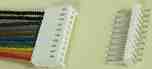 Multiple cables with snap lock headers:
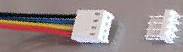 Multiple 4 pin 22 AWG 11" cables in sets of 2 with
1 (one) snap lock header: # 4Axis2c11M4 $3.00 each
cable (two per axis)
Multiple 4 pin 22 AWG 11" cables in sets of 2 with
1 (one) snap lock header: # 4Axis2c11M4 $3.00 each
cable (two per axis)
The assembly documentation is listed here in the order that the kits should be assembled assuming ALL the options are being installed. Skip the sections you don't want, but be sure to assemble in the order presented here: The order of assembly is important as some parts can not be installed after others.
All the reference designators (e.g. R3, J1, S1) are marked on the PCB as close to pin 1 of that part as is possible.
Pin 1 always has a square pad.
When soldering, use a sharp tip and as high a heat as possible. The solder should be standard flux core and as fine as possible. Hold the solder at the point where the lead and the pad on the board meet, then apply the (just cleaned) iron to the other side, again, at the point were the lead and the pad meet. Ensure there is solid contact between the solder and both metal parts, as well as the iron tip and both metal parts. A slight grinding or twisting motion of the iron can be helpfull. As soon as the solder melts, or in a few seconds if it doesn't, remove the iron and allow the joint to cool as long as possible. When soldering multi-lead parts like the 555 chip, mode switch or DB25 connector, to avoid heat build up in the plastic case, do NOT proceed in order, but rather always solder what would logically be the coolest lead next. Stubborn points can be eased with a bit of flux dispensed from the point of a pen or pin.
DB 25 connector
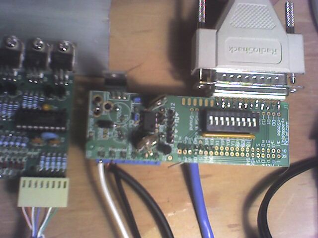
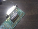
This MUST be a female connector. If you recieved the wrong part in error, please contact us for a replacement.The DB 25 connector is pressed onto the edge of the PCB. It is positioned starting from the corner of the PCB. The additional pads at the other end are for an optional 36 pins Centronics connector which proved to be very hard to source and expensive. Be sure that the pins aline with the pads (it will only align one way) and then work one end on, and slowly rock back and forth to spread the rest of the pins until the PCB edge is fully pressed against the plastic of the connector.
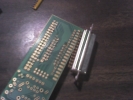
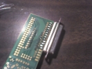
Check the pins for alignment to the pads, both top and bottom and re-position as necessary.
Solder each pin, with the iron touching the end of the pin and the pad and the solder fed from the side, near the body of the connector.
Mode Select Switch and Resistor Network
Insert the 9 position DIP switch (or 4 position combined with 5 position DIP switches) and solder each pin. It helps to "tack" one pin on each corner while holding the part in as it can easily slip out unexpectedly.
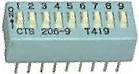
Some kits will have a single, 10 pin (9 resistor) network. If so, insert it with the marked pin in the square pad by the R3 designator and solder each pin.
The kit may, instead, have a combination of a 5 pin, 4 resistor network and another 6 pin, 5 resistor network. Insert both, but ensure the marked pin on each is as far away as possible from the other resistor. The marked pins should go in the holes marked with the arrows in the picture below.
On the first version of this PCB, there is a fault: The ground pins for the Y and Z axis on J5 are not connected to ground! The fix is easy: Just bridge from the X and A axis ground pins. This has been corrected on later versions.There are any number of ways to cable from the 4 axis board to the Linistepper controllers. Being able to remove a Linistepper board for repair or replacement may be worth extra effort. The Linisteppers are pretty solid, but they CAN be destroyed and having a spare to keep your machine up is probably worth it. Each linistepper kit comes with pins that can be crimped and soldered to a wire and housings for those pins to be installed into to make a nice cable for easy disconnect and re-connect.
The control and +5 power requirements are minimal so just about any wire can manage the load. Cable length may be an issue with high speed stepping so no more than a foot or 10cm is recommended.
Multiple 8, 9 or 10 pin (or 4 pin in sets of 2) 22 AWG cables with snap lock header. These are simple, effective, but more costly options for connecting the linistepper controllers seperatly to the 4 Axis board.
The easiest way to assemble this option is to simply solder the wire ends of the supplied cables to the 4 axis board and plug the connector on the other end of the cable into the Linistepper control single header. You can use the polarized snap lock header on the Linistepper board in place of the supplied RA header pins by clipping off the extra pins to match the 7 holes provided. This will help ensure the wires are connected in the same order on both ends. Note that there are more wires in the cable than needed. You can clip out the extras and plug the holes in the connector to prevent confusion. Because the 22AWG wires are pre-tinned, you may need to form some of the ends with pliers to get them to fit throught he holes on the board. In some cases, where the wire was not twisted well before tinning, you may need to clip off the end, re-strip, and twist tightly before the wire will fit in the holes.
The other option is to use the snaplock header supplied with the cable on the 4 Axis board and crimp, then solder, the pins supplied with the Linistepper kit to the wire end of the cable. In this case, extra care will be required to ensure the connections are never made backwards. On the first and second versions of the board, the snaplock headers are too wide to fit on the same side of the 4Axis PCB; one must be installed on the top, and the other installed on the bottom. The second one will be difficult to solder due to the interferrence of the first one, so be sure to solder the first one in place up a little from the surface of the board. On the third or higher board versions, another row of holes has been added so that the snaplock headers can all be installed on the top of the board, as long as the outside rows are used and the middle row left empty.
In either case, take care to notice that the order of the pins on the 4 Axis board is the same for each axis, but run in different directions for the "A" and "Y" axis than they do for the "X" and "A". "X" starts at the upper left of the picture below and runs to the right, as does the "Z" axis below it. The "A" axis is "upside down" in the upper right corner of the picture and runs to the left as does the "Y" axis below it. The lables for the mode switch and a much needed via interfere with some of the labels, but they are just the same as the pins on the axis below them.
 +5 Power kit.
The Power kit provides regulated +5V supply for the Linistepper controllers internal use from an unregulated DC power source such as the motor power supply. Assembly is easy:
Mount the diode first. The black band goes in the hole farthest from the edge of the PCB.
Ensure the power regulator is in as shown on the solder mask; with the back to the outside of the PCB.
Be sure to mount the capacitors with the longer lead in the hole closest to the "+" outside the circle.
The long lead of the LED needs to be in the hole toward the resistor. The resistor is installed upright; with one lead straight down through one hole and the other bent around and back down through the other hole
The PCB has a place for an AC adapter plug (J2), but it is supplied with the screw terminals for 9V Ground and +5V (opposite side of the PCB from J2) instead. In order to bypass the plug, the pad nearest the corner must be jumpered to the plug pad that connects to D1. This is shown on the figure under the text "shunt."
The 555 kits provides a test pulse for the step line so that you can verify operation of the linisteppers without having a computer hooked up. It can also be used in applications where only simple rotation is needed, such as telescope drives, display rotation, or short event timing. Please note that 555 timers are not terribly accurate time sources over the long term.
The 555 components must be placed and soldered before the relay if you are building both.
The leads on the 555 chip will probably need to be aligned with the holes by pressing the rows together or spreading them apart a little. Probably the easyist method is to insert one row a bit into the holes on that side and then use a fingernail or other semi flat object to press the second row down until those pins also go into thier holes. The 555 chip is pretty hardy, but it would be best to solder alternate pins to prevent heat damage and to limit the amout of static electricity by grounding yourself regularly.
Install these either way, they are not polarity sensitive.
Resistors
The two small variable resistors supplied with the kit may need to have their leads reformed before they will fit in the holes on the board. Finding a reliable source of low cost trim pots with square or round leads is difficult and providing multiple holes allows us to use several different foot prints, but requires that each hole be fairly small to avoid the drill popping from one hole to the next. If the leads don't fit in the holes, just smash them into a shape that will! Since the metal used in the leads is fairly soft, this isn't as difficult as it may sound at first. Simply use a pair of pliers with serrations or a rought surface and grip the lead so that the wider surface is perpendicular to the pliers inner surface (see picture) then squeeze until the lead is "smashed" into a less rectangular, more square, shape.
This option is not available on the first version of the PCB.
There are a number of other things you can do with the 4 axis board. For example:
 An important note is that the signals after "Sel"
are only connected to the PC parallel port if a 36 pin "centronics" solder
cup connector is used on the PCB and that is NOT supplied with the kit. The
much lower cost DB 25 connector has the same pin out up to pin 13 (Sel) and
the rest of the pins are never driven high by the host, so they are ok when
they wrap around to the ground pads on the other side. With the DB25, there
are still 4 input signals available (nAck, Busy, PErr and Sel).
An important note is that the signals after "Sel"
are only connected to the PC parallel port if a 36 pin "centronics" solder
cup connector is used on the PCB and that is NOT supplied with the kit. The
much lower cost DB 25 connector has the same pin out up to pin 13 (Sel) and
the rest of the pins are never driven high by the host, so they are ok when
they wrap around to the ground pads on the other side. With the DB25, there
are still 4 input signals available (nAck, Busy, PErr and Sel).
See also:
PS2 internal cable? Cut off the end?
Berg type connector?
SIP header cable?
Questions:
Comments:
I wish the schematic had *all* the component values on the resistors and capacitors. The silkscreen has some values that are missing on the schematic, and some other values are missing on both! Really, values should be only on the schematic, not on the silkscreen (to reduce silkscreen's clutter.)
James Newton of Massmind replies: First, please use the instructions at the new page. This page is for a prior version of this board.
The component values that are not specified on the schematic are either not critical (e.g. back EMF diode on the relay driver circuit) or depend on the users application (e.g. the component values in the 555 circuit). If we missed something other than those, on the current page, please do let us know. I'm happy to add values if doing so will not cause more confusion.
As far as clutter on the silkscreen, it seems readable and more information is better than less. If other people complain, we can reduce the markings on the next version.+
Kurt R Arnlund of kurta Says:
It should be mentioned that you should use a female DB 25 connector and a straight through male to male DB 25 parallel cable. This is very important because if you use a DB 25 male to female cable and a male DB 25 connector on the "4 axis / 555" board you will wind up with all the connections reversed right to left and it won't work.+
| file: /Techref/io/stepper/linistep/4axis2build.htm, 22KB, , updated: 2011/4/26 17:43, local time: 2025/6/18 16:37,
216.73.216.205,10-3-86-203:LOG IN
|
| ©2025 These pages are served without commercial sponsorship. (No popup ads, etc...).Bandwidth abuse increases hosting cost forcing sponsorship or shutdown. This server aggressively defends against automated copying for any reason including offline viewing, duplication, etc... Please respect this requirement and DO NOT RIP THIS SITE. Questions? <A HREF="http://www.sxlist.com/techref/io/stepper/linistep/4axis2build.htm"> Linistepper "4 AXIS / 555 / PWR" kit</A> |
| Did you find what you needed? |
Welcome to sxlist.com!sales, advertizing, & kind contributors just like you! Please don't rip/copy (here's why Copies of the site on CD are available at minimal cost. |
Welcome to www.sxlist.com! |
.