Adjustment
of Ultrasonic Range Meter unit
I think that the direction of the mounting is being careful sufficiently when you mount each part. However, there is possibility to make a mistake carelessly. Confirm the situation once more after finishing the part mounting. When using the IC socket, the direction of the mounting of the IC is sometimes opposite. Be careful. Confirm the soldering by the watching. When using the IC socket, confirm the power supply voltage before mounting the ICs. Connect the voltage of +12V to +30V to the power supply terminal from outside. Confirm that the voltage of the power supply pin of IC1-IC9 is +9V. IN CASE OF NOT BEING +9V, STOP THE POWER SUPPLY AT ONCE. Check whether or not there is not solder bridge. First, you do the following setting in the condition to have cut the power supply. Remove the IC1 from the socket and make connect the 1st pin and the 3rd pin by the short circuit wire(The remainder of the lead wire of the part). With this, the 1st pin of the IC3 becomes the L level and the 4th pin of the IC2 becomes the H level. The ultrasonic becomes continuously sent out when the 4th pin of the IC2 becomes the H level. Mount the IC4 of the receiver. Prepare the monitoring the voltage of the 1st pin of the IC4 with the oscilloscope or the high frequency detector. Turn on. Put the ultrasonic sensor in front of the wall and the transmitted ultrasonic makes be received with the receiver sensor. While monitoring the output of the IC4, turn the VR1 slowly and the output of the IC4 maximizes. The place to have been maximized is the resonant frequency of the transmission sensor. After this, it makes not move. Above, the adjustment of the transmitter is the end. After switching off the power supply, remove the short circuit wire of the IC1 and mount the IC1. Turn on and monitor the output of the IC4 again. Because the transmission of the ultrasonic gets not to be the continuation when mounting the IC1, the output of the IC4 falls. When using the oscilloscope, you can see the burst wave from.
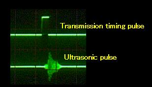
The ultrasonic pulse of the photograph above was observed on the side of the receiver. Generally, the adjustment isn't necessary but when having mis-detected the transmission pulse, change the capacitor(C11) into the big one. When mis-detecting, the display doesn't change as much as 0.40 even if it measures more than several-m distance.
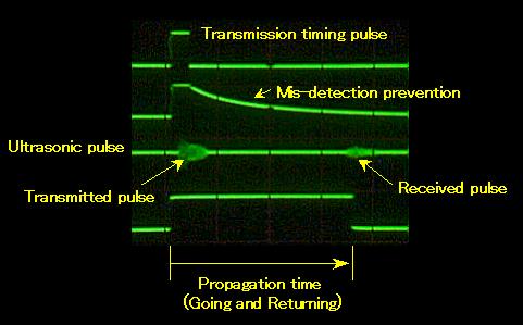
The photograph above is the one to have observed the signal wave from when measuring the about 2-m distance.
Adjust the frequency of the measurement pulse using VR2 and VR3. You do this adjustment after housing the equipment in the case finally.  When adjusting experimentally, it is convenient when using the short-circuiting pin instead of VR3. The cardinal point of the measurement of the range meter is the position of the diaphragm of the sensor. In case of the sensor which was used this time, the diaphragm is in the about 5-mm position from the bottom of the sensor. This position becomes the cardinal point. Stand the board perpendicularly in the place which left 1-m form the cardinal point of the sensor. Make the position of the VR3 the center and turn the VR2 and adjust for the display to become 1.00. When the ambient temperature changes, while measuring the 1-m distance adjust for the display to become 1.00 by turning the VR3. |