Introduction
This document describes how to generate composite color video signals in
software using an SX microcontroller. First the document describes the video
signal and after that how to do it in software.
There is also a PDF-version
(1.85MB) of this document, that is better if you wnat to print it to paper.
(Note: The PDF-file also contains the games pong and tetris with source, so
you might not want to print the whole document, also note that the document is
supposed to be printed on both sides of the paper making some of the even pages
are empty)
Index
Background
 |
|
PIC16F84-based Pong. |
 |
|
PIC16F84-based Tetris |
Back in early 1998 I made some experimenting using a PIC16F84 microcontroller (3MIPS of processor power) to generate composite B&W video signals on the fly in software, with two resistors as the only video hardware. I made the two classical games Pong and Tetris with this technique and published them including source on my homepage. Since then it has been built by several hundreds of people. During the Christmas 1998-1999 I got some equipment from Scenix (nowadays known as Ubicom) and made some experiments to generate color video signals using an SX chip, but before I got any results my programmer broke down, at least that was what I believed, and I stopped developing it. In the early summer of 2001 I was told by people at Parallax that it was the early versions of the SX-chips that had a bug in them so my programmer was just fine, so they gave me some new chips and I continued my work. After some new experiments, calculating and many late hours and a bit of luck I got my TV to lock onto the color signal an d by the end of summer I got a Tetris game up and running. During the fall I developed the Pong game, which was finished during the Christmas holidays 2001-2002. I didnt release the games as there were some details left to take care of. I didnt want to publish them until they were as perfect as possible due to my bad experience with my PIC-based games that were spread in early bad versions. Now in spring 2003 I decided that I shouldnt do any more improvements of the games as I dont have time to work on them and I got to stop sometime. The biggest remaining issue is that it only works good for NTSC, it is much harder to get a correct PAL signal in software, but that is a problem for someone else to solve. Another issue about the games was this text about generating color video signals that I wanted to finish before I released the games, to not get that many questions about video generation that I dont have time to answer. After reading this document you will hopefully understand how to generate color composite video signals in software. To fully understand this you need mathematical knowledge at university level, some RF-knowledge would also help a lot.
 |
 |
|
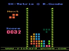
SX-Tetris. |
SX-Pong. |
The composite video signal
To understand anything about generating video signals in real-time, one must know how video-signals work in detail, so before we look at any code we'll have to talk about video signals.
How a standard TV-set works
 |
 |
| The electron beam drawing the screen. | The two part images becomes one whole image. |
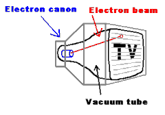
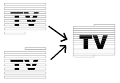
A standard TV-set is built with a vacuum tube, which has a phosphor screen that an electron canon shoots at. When the electrons from the cannon hits the screen, light is emitted from the phosphor when the canon shoots electrons at it, and it also has a short afterglow making each pixel lit until the electron beam hits it again. The electron beam from the electron-cannon can be bent using magnets so it shoots at different parts of the screen. If this is controlled so it draws horizontal lines all over the screen repeatedly, while the intensity of the beam is modulated, an image can be drawn on the screen. The screen is redrawn 25 times per second (on a PAL system), but to reduce flickering the image is interlaced, showing first all odd lines then all even lines, so the image is partially updated 50 times per second. To get color each dot on the screen is divided into three colors: red, green and blue.
Different TV standards
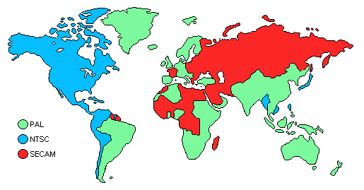 |
| A rough map over the different TV-standards used on earth. |
There are three major analog TV-standards: NTSC, SECAM and PAL as seen on the map above. The NTSC (Short for "National Television System Committee", but back in the early days of TV there was problems with getting the same color over the whole picture so a more evil interpretation of the letters is that it stands for "Never The Same Color" ) is the American TV-standard, it has only 525 scan-lines, but it has a update frequency of 30Hz. SECAM (Short for "Sequential Color And Memory", but as the French usually want to get their own solution to problems, a more evil interpretation is that it stands for "System Essentially Contrary to the American Method") is the French TV-standard, it has improved color stability and higher intensity resolution but with less color resolution, I don't know much about that standard. The European standard is PAL (Phase Alternating Lines, or as a PAL enthusiast would interpret the letters: "Perfect At Last"), it has 625 lines per frame, 25 frames per second. It is based on NTSC, but the color-coding has been improved by using a phase shift on every other line to remove the color errors that occurred with NTSC.
The information in the video signal
The image seen on the screen
has different intensities. As the electron beam sweeps over the screen, the
intensity that should be at the position of the beam, is sent as a voltage level
in the video signal. There is no information in this intensity information about
where the electron beam is on the screen. To solve this, a synchronization pulse
is sent in the beginning of each line to tell the TV that the current line is
finished and move down the electron beam to the next line. (Like the
Enter key on the keyboard, when writing a text with a computer) The TV
must also know when a new image is coming, this is done by making a special
synchronization pattern. (Like the "new document" function when writing a text
with a computer) An image that is updated 25 times per second would be quite
flickering, so therefore all even lines are drawn first and then all odd, this
method shows 50 half images per second, making the picture have less flickering.
The information whether the image contains even or odd lines are sent in the
vertical synchronization pattern, as different patterns for odd and even images.
The video signal has a voltage range 0 to 1V, where 0.3V represents black, and
1.0V is white (gray intensities have voltages between these values). Levels
close to zero represent synchronization pulses.
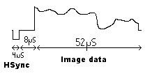
"Oscilloscope"-piture of one scan line
The scan-line
The image is divided into scan-lines, it is the most
important part of the image since it contains the image data. The scan-lines are
all 64us long. First a 4us long sync pulse is sent, by setting the signal level
to 0V, to tell the TV that a new line is coming. The old TV's was kind of slow,
so they needed 8us after the sync-pulse to get the electron beam in position.
During this time the signal is kept at black level. The 8us delay is followed by
the image data for 52us, drawn on the screen from the left to the right with the
intensities obtained from the video signal. Black is represented by 0.3V and as
the voltage increases the intensity increases, with the maximum intensity at
1.0v (white). See the image right to see the scan-line. The color information is
added as two amplitude modulated sinus waves, well get back to that later.
Putting the scan-lines together to an image
An image is built from
625scanlines, but a TV doesn't show 625 lines. Some of the lines are used for
synchronization pulses, and some lines are invisible (I don't know exactly how
many) because old TVs needed some time to move the electron beam from the bottom
of the screen. (Those invisible lines are nowadays used for other purposes,
Text-TV for example).
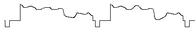 |
| "Oscilloscope"-picture of several scan-lines in a video signal. |
Vertical synchronization pulses.
To tell the TV that a new image is
coming, a special pattern of synchronization pulses is sent. Since the picture
is built from two half pictures, the pattern is different for the odd and even
images. The vertical synchronization pulses looks like this:
 |
| This picture shows the different vertical synchronization pulses for the two half images. The levels are 0v and 0.3v. Numbers below signals shows scan-line number. (Click to enlarge) |
Color coding.
When color was introduced, it was the same problem as
with any change in technology, there is always a demand for backwards
compatibility that limited the new technology. For video signals this meant that
a color video signal should look very much like a B&W signal so old TVs
would still work. The problem was solved by overlaying the color signal with an
amplitude modulated carrier on top of the video signal. In average the video
signal would still be the same for B&W and it would not be noticed if the
carrier had high enough frequency and the modulation also was kept to a low
bandwidth.
The intensity of the TV signal is the sum of the Red, Green and Blue parts (weighted with the eyes sensitivity coefficients for those colors) in the video signal, and since that information is already given in the B&W signal then the additional color information only needs to contain two components with color difference. With the intensity sum and the two components G-R and G-B, it is possible to derive the R,B and G values. Humans have higher resolution for light intensity than for color, so using higher bandwisth for intensety than for colr variation is very appropriate. Limiting the color information to two components is especially great as it is possible to transfer two signals using quadrature modulation, making it possible to transfer color using only one carrier overlaid on the B&W video signal!
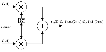
The basic principle of quadrature coding.
Quadrature modulation
Quadrature modulation is a general method for
modulation of a carrier. The idea is to change both amplitude and phase of the
carrier to be able to send two signals with one carrier frequency. Each signal
has its own carrier, one is sin (2pi*fc*t) and one is cos (2pi*fc*t), which
makes it possible to reach all phases and amplitudes by modulating the voltages
of the two signals. This method is not only used for TV color modulation, it is
widely used, for example this is how stereo information is sent over radio also.
It is a clever way to use the bandwidth to the maximum, with standard amplitude
modulation only one channel is used, the other is just wasted. In order for this
method to work, there must be a pilot, a reference signal that makes
synchronizes the oscillator in the receiver with the one on the transmitter.
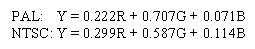
How the quadrature modulation is used differs slightly between PAL and NTSC. One variation is the white level as PAL where developed after NTSC and has hence more accurate coefficients to the newer more luminant phosphors used inmodern CRTs. The colors are weighted according to the eyes sensitivity, so the green color is weighted the most, blue the least and red in the middle. Using RGB-color levels detected by the video camera, the luminance is calculared according to:
The Y,U,V component transformation can be described as a matrix, for PAL the matrix looks like the following:

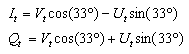
In NTSC the U and V components are rotated 33 degrees to minimize bandwidth for Q, the rotated components are called I and Q, calculated according this:
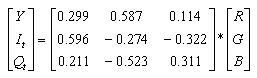
For NTSC the Y,I, Q components can be described using the following conversion matrix:
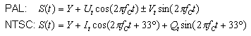
Putting it all together
The output is created with quadrature
modulating as described before by modulating a cosine and a sine with the U and
V (I and Q for NTSC) components and sum the result together with the lumination
component Y. For PAL there is also a change in sign of the sinus component to
compensate for phase error that will take out each other. (That is why it is
called Phase Alternating Line). The video signal is calculated according the
following:
So the color coding is just as simple as that, but there is one detail left, there must be a pilot signal in order for the quadrature modulating. In most systems using quadrature modulation, the pilot signal is sent constantly as a tone in the signal, for TVs however that would disturb the image too much. If there is an oscillator in the TV that is very stable, it would be enough to send a couple of cycles of the pilot periodically for the oscillator to tune in to, just often enough for the oscillator to keep its phase. In the B&W signal there is a gap of about 7us between the sync pulse and where the image information starts, so it was an obvious place to put the reference carrier. This is 10-12 cycles of the color carrier (amplitude of 20IRE = 0.15V) and referred to as the color burst. The color burst is also shifted +-45 degrees on every scan-line for PAL.
 |
| This picture shows the scan lines including color burst. (Click to enlarge) |
How to do it in software
Generating a B&W signal is not very complicated; it is just hard work as it is a question of counting clock cycles to make the program flow take exactly the same amount of clock cycles all the time. When doing a color signal, this is even more important, if the line is one cycle too long or short (An error of 0.03% in scan line length) the TV cant lock to the color carrier at all, for a B&W video signal the timing is not this critical, most TVs can compensate for quite large errors in a B&W video signal, so you could make the scan lines length several tenths of cycles wrong without noticing as the TV compensates for it, but as our goal is to make a color video signal we are not allowed to do any errors at all. To make the job of timing easier Ive created a general delay macro that delays for a given time using a minimal amount of program memory. Ive also tried to use a lot of EQU-constants to make the code more readable and make the code possible to run for both NTSC and PAL by only changing the constants so the code is the same for both systems.
The first thing the software needs to do is output the vertical sync pulses, to tell the TV that a new frame has started. Then for the following 304 lines (254 for NTSC) it should keep each line 64us long and start each line with a horizontal sync pulse. Later on when doing a color signal a color burst must also follow after the horizontal sync pulse. During the 52us of image time the software needs to vary the voltage of the video signal between 0.3v (black) and 1v (white) as the electron beam sweeps over the screen and try to do draw something as the electron beam sweeps over the screen. This is quite easy with an SX performing 50MIPS, Ive done B&W games this way using a PIC16F84 performing 3MIPS, so one could do B&W games with quite high resolution using an SX. However, generating color is much more cool, so lets talk about color generation now.
The basics for color generation
As you would know after reading the
chapter about video signals, the software needs to create modulated sinus and
cosines waveforms for color information and sum them together with the intensity
waveform. To get a good result the sample rate needs to be much higher than the
color carrier frequency, and the software must also be able to do the needed
calculations for the waveform which in total would need a very powerful
processor if there is no hardware to help. An SX processor performing 50MIPS
would not be good enough using this method.
Mathematical tricks
However, there is fortunately a better way to
do it. The color carrier part of the signal is the sum of a sinus and a cosines
with the same frequency but different amplitude, this is very fortunate as the
cosines could be rewritten as a sinus with it phase shifted 90 degrees compared
to a cosines. Ok so what good is that, well, the sum of two sinuses with same
frequency and fixed phase difference but with varying amplitude could be
rewritten as one sinus with alternating phase and amplitude according to:
 |
| The coefficients preceded cos and sin describes a point on the unit circle and could be replaced with cos and sin with the angle alpha according to: |
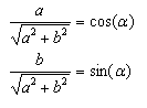 |
| This equals a rotation by an angle alpha according to: |
 |
| Making it possible to express the sum of an aplitude modulated sin and cos with one sin that is both aplitude and phase modulated. |
Know your hardware
Ok we got rid of one of the components but still
have one sinus that needs to be generated requiring a lot of CPU power. At the
input of a TV there is a low-pass filter to limit the signal within a video
signals allowed bandwidth of about 5MHz, which is very good because that means
that a square wave at the color carrier frequency would look like a sinus to the
TV as the high frequency components of the square wave have been filtered away.
Now we are down to a square wave with changing phase, amplitude and offset,
which is possible to generate in software with an SX@50MHz if the number of
phases is limited and the clock frequency is a multiple of the color carrier
frequency. In my projects I clock the SX with 12 times the carrier frequency for
both PAL and NTSC, which gives 53.156550MHz for PAL and 42.954540 for NTSC, the
over clocking of a 50MHz SX chip to 53MHz in the PAL case seems not to be a
problem at all.
Our new parameters
The simplified signal with the square wave works
like this: The average voltage of the signal control the lumination, the
amplitude of the signal controls the whiteness and phase controls the color.
When using 12 times the color carrier it is possible us get 12different colors
with different variation in intensity and whiteness. The first test I made with
color generation was to examine the 12 base colors available, this test I shown
in the picture to the left below. The source is available here in test1.src
(This is the only one of my current programs actually performing phase
alternation in PAL, sp the phase errors for PAL are not visible in this example)
All possible variations for the 12 base phases can be seen here to the right
below where all possible values for first and second amplitude are shown for all
12 phases and five bits. (There are25*25*12/2-25*5=3625 combinations) The source
for the later is available in test2.src
 |
 |
| The 12 phases, generates these 12 base colors. (Click to enlarge) | The available colors for 5bit DA and 12 phases. (Click to enlarge) |
Phase Alternating Line
is what PAL stands for, and that is a
problem, when generating a PAL signal one should switch the phase of the signal
180degrees on every line (color burst switched 90 degrees), this is not possible
with the method I generate color signals. It is possible to produce more simple
graphics such as one colored horizontal lines and phase alternate, but when
doing more complicated stuff (like text or graphical objects) t becomes a
problem as not only is the phase alternated, so is the positions of the graphics
as the graphics must be aligned with the color carrier cycles. I chose to solve
this by ignoring the phase alternation, with the downside that it makes phase
errors visible as they did originally with NTSC where there is no phase
alternation. With NTSC this is no longer a problem as the modern TVs have become
better and lock to the color carrier much better, which the PAL TVs didnt have
to as their color method compensated for this problem, giving me a problem when
I cheat when generating my video signals. I have no good solution for the
problem with PAL to be software generated; it is up to someone else to figure
that one out. (All pictures in this document are from the NTSC versions as they
are the only pictures that are good enough to digitize with the TV-card in my
computer)
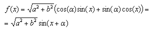
Video output hardware
To be able to generate the signal we need a
DA-converter. To make this simple a resistor based DA is the way to do it. There
are two kinds of resistor DAs, 2N-nets and R2R-ladders. The 2N net is the
simplest solution, it looks like this:
 |
| 2N DA converter schematic. |
The downside with the 2N-net is that it is very inaccurate; the R2R-ladder requires twice as many resistors but has much higher accuracy, it looks like this:
 |
| R2R DA converter schematic. |
First I chose 6 bits for the DA as that is the largest number of bits that would be useful using 1% accuracy resistors, later I found that five bits is enough, the extra bit is better off in the DA, so the finished system go five bits for both sound and video. The video bits is bit 1 to 5 in my system as I already had done a optimizations in the code for using the lower 6 bits of portb making it the easiest solution, but when designing I new 5 bit system it is of course better to use bits 0 to 4.instead. Output voltage should be in the range 0 to 1.25V, which sets the values of the resistors to 220 and 440.
Limitations with colors
The color bandwidth is very low so it is
not possible to change colors fast. In my games I keep the color phase constant
within a graphic object and only change lumination level once every color cycle.
This gives a maximum resolution of 2766/12=230 pixels per scan line for PAL and
2233/12=186 pixels per scan line for NTSC. In reality not all pixels can be used
as color (phase) changes cost time and thereby color cycles, and then the
graphics also has to be calculated to there are not all of these pixels that
actually can be used.

Monochrome ball from Pong.
Use of Palette
To save memory a palette is often used in computer
graphics cards. A palette is basically a color lookup table. In most cases the
palette contains 2N colors, usually 16 or 256 colors to be able to get each
color into a nibble or a byte. If a picture only uses 16 different colors, then
it needs 6 times less memory compared to if each byte would have been stored as
three 8bit values with the RGB-components if a 16 color palette is used. In my
games a palette is used to need less data for some of the graphics, a 16 color
palette is used, however the lookup table doesnt store the RGB values, instead
it stores high and low period values for the square wave. In other words, my
palette only contains info on brightness and whiteness, the color is set by the
phase of the square wave which is not stored in the palette. Only one palette is
used for both my games and it stars at black level, moves to color with maximum
intensity, and then moves to maximum white. (See diagram below.) This palette
makes it possible to generate objects with a 3D-feeling as it is possible to
make dark shadows and more illuminated parts within the same object, but the
object must be monochrome. It is possible to generate palettes with a 180
degree phase shift and get the complimentary color, but as the bandwidth is
limited it is not possible to mix colors from the two phases in any order, it
takes almost one color cycle for the phase change. (If the graphics is carefully
planned to get few phase shifts, this could probably be used to do some really
cool two colored objects)
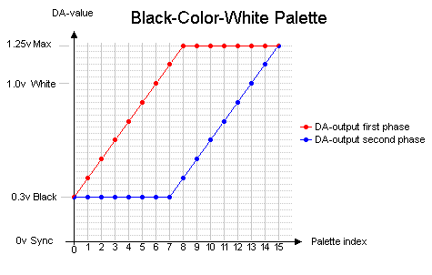 |
| The BCW-palette used for monochrome objects in my
games. |
Outputting monochrome objects using palette
When showing graphics
with high resolution (one intensity change per color cycle) it is not possible
to calculate the graphics in real-time, so the graphics needs to be
pre-calculated and stored in a buffer and then outputted from the buffer. I have
created a routine that gets 4-bit graphics from the upper nibble in program ROM,
translates it using a palette and store it in a buffer, consuming 31 clocks per
pixel. A matching output routine, called memtovideo, which outputs data from the
buffer at a speed of one pixel per color cycle (12 clock cycles). During the
calculation of the next object it is not possible to show any graphics except
for black or different gray colors, so therefore the layout of the graphics is
very critical. In my Pong game I use three different graphic buffers, one for
each paddle and one for the ball, and the graphics calculation is dynamically
changed depending of where the ball is on the screen because the ball position
controls where on the screen there are black surfaces that can be used for
graphics calculations. In Tetris the graphics for the screws beside the graphics
is calculated to the right of the playfield on the line above the one where the
graphics is shown, and as both screws are identical only one graphics
calculation is needed but it is outputted twice (one time on each side).
Colored text lines
The texts that appear in my games are generated
on the fly; only two ROM-accesses are needed per character. First the character
is read from the string stored in program ROM (low 8 bits), then this is used
together with the line number to find the graphics from the font that also is
stored in program ROM. Each character is 7 pixels wide, and separated by two
pixels, originally the separation was three pixels but after unrolling the loop
I got it down to two pixels (At the cost of program memory usage). The
separation could probably be decreased to one by more unrolling at the cost of
more program memory. A font is quite expensive in memory usage, so to save
memory I only store the characters I use. The color generation in the text
output is done by having a high and a low level for each pixel, the high level
is an input parameter and the low level is always black to optimize the
routine.
My games
I have made two SX-based games, Pong and Tetris, generating a composite color video signal in software:
|
|
|
|
SX-Tetris |
SX-Pong |
Emulators
When making this kind of software ios is good to have emulators. There are unfortunately no emulators yet, but there are some open source emulators for my previous pic-games. (For example the PIC16F84 emulator by Jesus Arias), there are also open source sx-emulators available (For example Loren Blaney's SxSim). These open source projects are a good start for making your own sx color video game emulator.
Conclusions
It is possible to generate composite color video signals in software, but it is a lot of work and it is only possible in some special cases. NTSC is much more easy to do than PAL when doing the signal in software as phaseshifting is better done in hardware. The main reason for doing video in software is doing it for fun and that it is possible =), this form of video generation has very little commercial value as it takes huge amount of time to generate something with very poor result. Doing software based monochrome signal colored with hardware would give better result, but the best result is of course done with memory mapped graphics outputted with dedicated hardware.
More info about video signals.
There is not much written on generating color video signals in software, but there some stuff written about generating B&W signals. If you want to know more about generating video signals check out some of these links:
Questions ?
If you have questions about the games, make sure to check out the FAQ (Frequently Asked Questions) before you ask me.
Copyright note
How to generate color video signals in software with SX-chips (C) Rickard Gunée. This is open source, use this at your own risk ! You may use the information on this page for your own projects as long as you refer to the original author (by name and link to authors homepage), don't do it for profit and don't hurt or harm anyone or anything with it. The author can not be held responsible for any damage caused by the information on this and related pages.