Microstepping Stepper Motor Driver Kit. This page is for theory of operation only. For operation instructions see the Users Guide and for instructions to build it, see the Assembly Manual.
History.
Cheap microstepping drivers seemed to be nonexistant.
I quickly made up a board that would suit my hobby needs and be
able to drive most motors fairly accurately and powerfully,
with cheap non-specialist parts (no stepper ICs).
Block Diagram;
+5v to +32v --------------------,
(depends on motor and |
what speeds required) |
|
| motor common (power) wire
| (motor must have 5,6,8 wires)
,---------*-------,
| |
,---*---, ,----*----,
| | | |
| | | |
| | | |
# # # # 4 motor coils
A+ | A- | B+ | B- | (arranged as 2 phases
| | | | unipolar)
| | | |
+5v----, | | | |
| C C C C 4 darlington power
brain-->---B --B --B --B transistors
| E E E E
| | | | |
^ | | | |
| '---*---' '----*----'
| | | 2 current-sense
'-------<---- Rs <-- Rs resistors, one for
| | each phase
| |
gnd -----------------*-----------------*-------------------
Basic design
It is a unipolar (or 5-wire type) driver. The motor must have
5 or 6 wires (or 8), as 4-wire motors are only for bipolar
and 4-WIRE MOTORS WILL NOT WORK WITH THIS BOARD.
The constant current system is crude but simple, it relies on
setting the base of the main transistors at a "set" level, then
this causes a "set" voltage across the sense resistor Rs, ie
maintains constant current. It does get some temp drift with
large currents, but it's simple and accurate enough with the
resistor values i've tested. It actually works quite well!
The brain has control of which of the 4 transistors are ON,
and sets 3 possible current levels, enough to do 6th stepping
and give 1200 steps/rev with hardware alone. The software I
have provided also will do pwm and give 18th stepping, which
is 3600 steps/rev, almost stepless operation.
The PIC has plenty of left over rom if you need to do motion
control or use the board as the complete brains and driver for
an entire machine. Up to 9 PIC in/out pins can be allocated to
the board.
Special Features
There is an RC filter in the linear microstepping circuitry that
will give fairly smooth "ramping" from one current level to the
next. At tuned speed this gives almost "sine like" smoothness and
quietness.
In all lower speeds, the linear current ramping does still have
some effect and ramps between steps more smoothly with less problems
from resonance and less ringing torque. Less ringing torque means
more available torque and quieter more powerful operation.
Circuit Diagram;
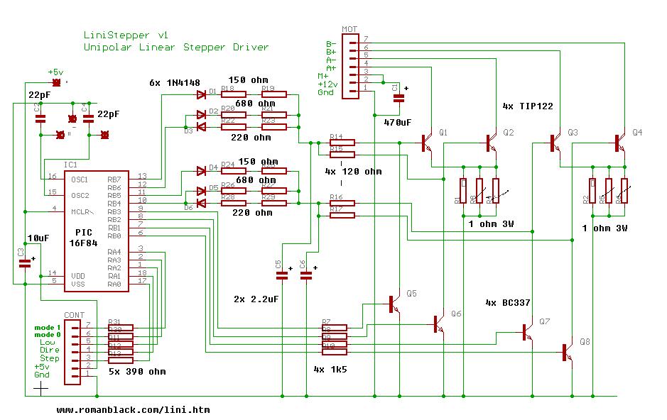 The circuit looks messy as it has provision to be wired in different
formats for different user requirements.
The 6th stepping needs 3 different current levels, and OFF,
and this is provided by 4 PIC outputs and some resistor ladders.
The value of resistors sets the 3 individual levels. This gives
1200 steps/rev in hardware alone, and software can modulate
between any two current levels to give "tween" steps chosen
in software. My software (supplied) does 200,400,1200,3600 steps.
C5 and C6 are the ramping capacitors.
Unipolar.
I chose this because it has advantage of making the circuit cheap
and much simpler and easier to build. Less parts, less soldering,
etc etc. Also a motor run as unipolar has half the inductance of
the bipolar wiring and can perform better at higher speeds.
It is also the configuration of most cheap "surplus" stepper
motors, etc etc.
Constant current?
Constant current is needed to set the small current levels needed
for microstepping. It also allows good high speed motor operation.
The board controls the current through the motor coils, regardless
of motor voltage or power supply voltage.
You can connect a number of different motors that have different
ohms etc, and the board will run them at the same (set) current.
The circuit looks messy as it has provision to be wired in different
formats for different user requirements.
The 6th stepping needs 3 different current levels, and OFF,
and this is provided by 4 PIC outputs and some resistor ladders.
The value of resistors sets the 3 individual levels. This gives
1200 steps/rev in hardware alone, and software can modulate
between any two current levels to give "tween" steps chosen
in software. My software (supplied) does 200,400,1200,3600 steps.
C5 and C6 are the ramping capacitors.
Unipolar.
I chose this because it has advantage of making the circuit cheap
and much simpler and easier to build. Less parts, less soldering,
etc etc. Also a motor run as unipolar has half the inductance of
the bipolar wiring and can perform better at higher speeds.
It is also the configuration of most cheap "surplus" stepper
motors, etc etc.
Constant current?
Constant current is needed to set the small current levels needed
for microstepping. It also allows good high speed motor operation.
The board controls the current through the motor coils, regardless
of motor voltage or power supply voltage.
You can connect a number of different motors that have different
ohms etc, and the board will run them at the same (set) current.
 6th stepping is done in hardware
Microstepping
Uses combinations of the 3 available current levels to give 6th
stepping, or 6 times as many steps as the motor has in full-step
mode. Additional software control by the PIC gives 3600 steps!
Good for science/robot motors to move in 0.1 degree increments.
(The stepper motor itself will not position accurately down to
one 3600th of a turn, but there is still good useful positioning
and many other benefits gained from the increased smoothness.)
Microstepping has less noise, and less resonance allowing
operation to very high motor speeds. If you have only used full
step and half step drivers before you will really enjoy
microstepping. If you write custom PIC software you can get
infinite angle control by controlling the 2 motor currents with
software pwm.
Linear?
Many people don't like them, and they are definitely not
fashionable in these days of throwaway bubblejet printers with
tiny stepper chips like the UCN5804.
But, linear stepper drivers give very good MOTOR performance,
especially when you need to accelerate to high motor speeds or
need smooth "stepless" operation at very low speeds. Torque ripple
from voltage chopping is removed, also gone is the supply ripple
from chopper recirculating currents. Expensive high-speed high-
current diodes are not needed. Eddy currents and copper losses,
and recirculating diode losses are reduced and the motor gets
LESS heating with linear than with a chopper supply, although the
driver gets more. :o)
Yes this driver does get hot, and needs a heatsink!
But I designed this for my needs, ie to be adaptable to any new
motor needs I have from 200mA floppy motors that need fine
microstepping, to large 2A motors etc. I thought it was better
to have "one board does all" than to use the expensive and
tiny stepper chips.
Think "large audio amp"...
- Linear is a great way of getting an exact-shaped high freq
current into something inductive like a speaker or motor.
Current Ramping
A benefit of linear, the analog current control has an RC network,
giving a "ramp" from one current step to the next.
Ramping rate between steps is selectable by the capacitor size.
Ramping is much better than hard edged steps, and reduces
excitation energy that causes "singing" and resonance. With ramping,
more of the motor energy is converted to forward rotation, unlike
the "two steps forward one step back" effect of hard ringing steps.
The ramping can be tuned for main operating speed to give almost
stepless operation and very quiet and smooth rotation. Analog ramping
takes no PIC processor time and can be set VERY slow so even slow
motor speeds like 0.5 rps can be made smooth!
No other cheap stepper driver does this!
| | |
|-----| |------
| | |
| | |
| | |
----| |-----|
| | |
Normal stepper driver.
(jerky, overshoots, resonant, noisy, reduced torque)
/-\ /-\
/ \ / \
\ / \ / \
\ / \ /
\-/ \-/
With simple analog ramping.
(more "stepless", less overshoot, smoother better torque)
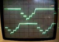
Here are the actual waveforms
(Shown is the DC current through the 2 motor phases. 1A = 2 vert div)
3 current levels, 1200 steps, no ramping (normal microstepping)
6th stepping is done in hardware
Microstepping
Uses combinations of the 3 available current levels to give 6th
stepping, or 6 times as many steps as the motor has in full-step
mode. Additional software control by the PIC gives 3600 steps!
Good for science/robot motors to move in 0.1 degree increments.
(The stepper motor itself will not position accurately down to
one 3600th of a turn, but there is still good useful positioning
and many other benefits gained from the increased smoothness.)
Microstepping has less noise, and less resonance allowing
operation to very high motor speeds. If you have only used full
step and half step drivers before you will really enjoy
microstepping. If you write custom PIC software you can get
infinite angle control by controlling the 2 motor currents with
software pwm.
Linear?
Many people don't like them, and they are definitely not
fashionable in these days of throwaway bubblejet printers with
tiny stepper chips like the UCN5804.
But, linear stepper drivers give very good MOTOR performance,
especially when you need to accelerate to high motor speeds or
need smooth "stepless" operation at very low speeds. Torque ripple
from voltage chopping is removed, also gone is the supply ripple
from chopper recirculating currents. Expensive high-speed high-
current diodes are not needed. Eddy currents and copper losses,
and recirculating diode losses are reduced and the motor gets
LESS heating with linear than with a chopper supply, although the
driver gets more. :o)
Yes this driver does get hot, and needs a heatsink!
But I designed this for my needs, ie to be adaptable to any new
motor needs I have from 200mA floppy motors that need fine
microstepping, to large 2A motors etc. I thought it was better
to have "one board does all" than to use the expensive and
tiny stepper chips.
Think "large audio amp"...
- Linear is a great way of getting an exact-shaped high freq
current into something inductive like a speaker or motor.
Current Ramping
A benefit of linear, the analog current control has an RC network,
giving a "ramp" from one current step to the next.
Ramping rate between steps is selectable by the capacitor size.
Ramping is much better than hard edged steps, and reduces
excitation energy that causes "singing" and resonance. With ramping,
more of the motor energy is converted to forward rotation, unlike
the "two steps forward one step back" effect of hard ringing steps.
The ramping can be tuned for main operating speed to give almost
stepless operation and very quiet and smooth rotation. Analog ramping
takes no PIC processor time and can be set VERY slow so even slow
motor speeds like 0.5 rps can be made smooth!
No other cheap stepper driver does this!
| | |
|-----| |------
| | |
| | |
| | |
----| |-----|
| | |
Normal stepper driver.
(jerky, overshoots, resonant, noisy, reduced torque)
/-\ /-\
/ \ / \
\ / \ / \
\ / \ /
\-/ \-/
With simple analog ramping.
(more "stepless", less overshoot, smoother better torque)
Here are the actual waveforms
(Shown is the DC current through the 2 motor phases. 1A = 2 vert div)
3 current levels, 1200 steps, no ramping (normal microstepping)
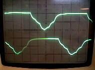 3 current levels, 1200 steps, with linear ramping!
 9 current levels, 3600 steps, with linear ramping!
That is a "sine-like" wave for almost stepless operation.
Operation of the constant current circuit:
Example: If voltage at point Vx is 2v (by the voltage divider),
Rsense is at (2v-1v)=1v.
If Rsense is 1 ohm the current is fixed at 1A as shown:
+12v dc
+5v ---------, |
| |
| |
,------, | Stepper
| | | coil
| | 4.5v out | |
| |------, | |
| | | | |
| PIC | R1 Rp |
| brain| | | |
| | | | C NPN Darlington
| | Vx *---*--B (1V b-e)
| | 2v | 2v E
| | | | 1v
| | ,--* |
| | | | |
| | C R2 R current
'------' | | | sense
'--* | 1v / 1ohm = 1amp
| |
| |
gnd ----------*--------*---------------
Also: A Java simulation of this circuit.
The capacitor across R2 gives the current ramping. No it's not
perfect ramping, but for a cheap simple solution it works ok.
With 6th stepping, the cap is always charged at the last level,
so when the step occurs the volts ramp smoothly to the next level.
Rp holds the transistor JUST off (at 0% current) when the PIC is
not sending an output, so any signal from the PIC will
proportionately increase the current past the zero point.
In this way the PIC sets 4 main currrent levels;
* 0% current
* 25% current
* 55% current
* 100% current
To make these levels tuneable I have provided a small prototype
area on the board where you can make resistance values by combining
two resistors in series. The resistor values I have chosen are to
give the currents above, give or take a few percent.
The hardware microstepping alone gives 1200 step operation.
In software the PIC can do modulation between any 2 of these levels,
giving "tween" current levels of any amount.
9 current levels, 3600 steps, with linear ramping!
That is a "sine-like" wave for almost stepless operation.
Operation of the constant current circuit:
Example: If voltage at point Vx is 2v (by the voltage divider),
Rsense is at (2v-1v)=1v.
If Rsense is 1 ohm the current is fixed at 1A as shown:
+12v dc
+5v ---------, |
| |
| |
,------, | Stepper
| | | coil
| | 4.5v out | |
| |------, | |
| | | | |
| PIC | R1 Rp |
| brain| | | |
| | | | C NPN Darlington
| | Vx *---*--B (1V b-e)
| | 2v | 2v E
| | | | 1v
| | ,--* |
| | | | |
| | C R2 R current
'------' | | | sense
'--* | 1v / 1ohm = 1amp
| |
| |
gnd ----------*--------*---------------
Also: A Java simulation of this circuit.
The capacitor across R2 gives the current ramping. No it's not
perfect ramping, but for a cheap simple solution it works ok.
With 6th stepping, the cap is always charged at the last level,
so when the step occurs the volts ramp smoothly to the next level.
Rp holds the transistor JUST off (at 0% current) when the PIC is
not sending an output, so any signal from the PIC will
proportionately increase the current past the zero point.
In this way the PIC sets 4 main currrent levels;
* 0% current
* 25% current
* 55% current
* 100% current
To make these levels tuneable I have provided a small prototype
area on the board where you can make resistance values by combining
two resistors in series. The resistor values I have chosen are to
give the currents above, give or take a few percent.
The hardware microstepping alone gives 1200 step operation.
In software the PIC can do modulation between any 2 of these levels,
giving "tween" current levels of any amount.
Questions:
I would like to use linisteppers to drive Vexta pk246 motors with encoders. They are 3 amp/phase in unipolar mode.
When ordering the kits - 4 axis - can you provide the parts that are needed for 3amp/phase operation as part of the kit ?
The description of use for higher amps sounds hesitant; do you advise against it ?
Is there a detailed post from someone that runs a 3 amp/phase motor with this card ?
James Newton of James Newton's Massmind replies: Sorry, I can not change the component values in the kit. But the power resistors you will need are commonly available at any electronics supplier.
At 3 amps, in microstepping modes, the power transistors on the Linistepper will get very hot. It is your responsibility to keep them cooled down enough that they don't burn out. In full or half step, heat will be much less of a problem.
A lot of people have run the Linistepper at 3, 4 or even 5 amps, but they used CPU fans or very large heatsinks and they tested it carefully under all conditions before they left it running. All the details on how to tune it for higher amperage are at: How to use it, and keep it cool!+
If I have a look to the schematic image http://www.piclist.com/images/member/RB-ezy-Q33/circuit.gif i see R14-R15-R16-R17 in series with the base of the four TIP122... Is it the right way to connect these components? In the costant current explanation it seem that the resistors should be connected to GND... Is something wrong in my idea or it's only a second "version" of the current controller circuit?
James Newton of James Newton's Massmind replies: The current limit resistors are R1 and R2. R14, etc...are the control / PWM resistors.+
can you explain how the sense resistors work, from the circuit it would appear the are current limiting only, how is the pic able to sense the apms/volts?
James Newton of James Newton's Massmind replies: The PIC regulates the current by changing it's outputs to the analog circuit. The circuit itself reacts to the changes in the motor and corrects the bias of the power transistors to compensate.+
Hi,
I really like your way of thinking on stepper motor control. I started out getting involved in model railroading, but my eyes have gotten so poor at age 66 that I decided to convert my small Myford lathe into a mill so I could drill holes more accurately. Then I started thinking about adapting CNC to it. This would allow me to program for repeat hole patterns etc.
What I want to know is if it is possible to adapt a 555 timer chip so I could have manual control for a small mill job or just to have a rapid traverse? This would also require direction control. Also, what provisions do you have for limit switches and home position? Thanks so much. Jack
James Newton replies: While your 555 mod should be possible, I would think this would be better supported via the PC software. Turbo CNC and others support joystick or mouse interfaces that run the motors under your manual control. Limit and home switches are also best supported by the software.+
Very nice! I have a question about the tuning of the linearity of the C-R2 circuit for different stepping speeds. If I put a digital pot between the C and the Base junction with R2, will that vary the charge time and let me tune on the fly? R(digital pot) would vary with step time and inverse with step size (longer time between steps == lower R, smaller steps == higher R).
Thanks
RM
James Newton replies: I would imagine so...
Looks like what I need, but first -- a bit of guidance. I want to drive and control, remotely, three needle valves. The inputs would be three potentiometers, giving some kind of voltage input to your control boards. Each board would control a stepper motor, geared or otherwise connected to a needle valve shaft. Turning the potentiometers from zero to max. would then turn the needle valves from fully closed to fully open.
This is obviously a low-power application, but will require fast response and frequent changes, up and down. The system will be in continuous duty, over a period of hours. I don't see any need for mode changes; we would presumably set it permanently in microstepping mode.
Questions:
1. Is this feasible, as it appears to be?
2. What would be the appropriate voltage to apply across the input potentiometer, and exactly how would that be applied to the control board inputs?
3. Recognizing that a needle valve requires several revolutions from fully closed to fully opened, how would the input voltage range be converted into several stepper revolutions? Would it be necessary to use gears, or can zero-to-max input produce, say, four full stepper revolutions?
4. Am I on the wrong track here? Is there a simpler and cheaper way to accomplish what I am trying to do?
Thanks for your advice. BTW, your presentation here seems outstanding, remarkably complete, and very clear. The apparent quality of your kit, and the user guidance, are excellent.
Kent
James Newton replys:
Answers by the number:
- Sure
- The linistepper (as is) does not respond to an analog signal but rather to step and direction digital inputs. You would have to either A) Change the programming of the on board PIC microcontroller to use an A/D converter and read the signal then generate step and direction commands for the existing stepper controler code, which you CAN do because Roman has made this an open source project, or B) build some other controler that translates the analog voltages into step and direction commands. A PIC or SX would be fine for doing that. Probably even a basic stamp.
- See the answer to #2. But there is no limit on the rotation of the steppers.
- It depends on what you really need. I think you are looking for a servo based system rather than steppers, because some servos can adjust position based on an analog input and it is easy to convert an analog input into the pulse width signal that standard servos accept, but the cost of a servo that is strong enough will probably be higher than the cost of a stepper and controller. Servos include feedback (which is not usually necessary with a stepper), electronics and gearing which increase the cost. Also, I haven't seen a servo that would do more than about 180' (they may exist, I just haven't seen one) so that requires gearing as you suspect. Finally, you may find that a simple 1:1 relationship between the analog input and the valve position is not what you actually need. In that case, haveing a microcontroller in there would allow you to vary the valve position as you wish.
Thanks for the kind words and good luck with your project.
Comments:
| file: /Techref/io/stepper/linistep/lini_wks.htm, 24KB, , updated: 2016/1/19 10:00, local time: 2025/5/24 07:37,
owner: RB-ezy-Q33,
216.73.216.48,10-6-7-222:LOG IN
|
| ©2025 These pages are served without commercial sponsorship. (No popup ads, etc...).Bandwidth abuse increases hosting cost forcing sponsorship or shutdown. This server aggressively defends against automated copying for any reason including offline viewing, duplication, etc... Please respect this requirement and DO NOT RIP THIS SITE. Questions? <A HREF="http://www.sxlist.com/Techref/io/stepper/linistep/lini_wks.htm"> LiniStepper, lini, stepper, linear, 6th microstep, linear microstepping stepper motor driver, constant current linear driver, circuit Linistepper boards, LiniStepper kit, hobby stepper, robot stepper driver kit, CNC stepper driver kit</A> |
| Did you find what you needed? |
Welcome to sxlist.com!sales, advertizing, & kind contributors just like you! Please don't rip/copy (here's why Copies of the site on CD are available at minimal cost. |
Welcome to www.sxlist.com! |
.