High Performance Steppers - Part 2.
How to measure Stepper
Motor torque.
Roman Black - Jan 2001
You can save this file to your hard disk and/or print it on
standard paper (save the pictures too.)
This work is free for private use. If you want to use it for commercial purposes
please contact me;
spamfastvid at ezy.net.au
This papers are a "how to" for getting maximum performance from your stepper motors without needing a huge budget. Focus is on hobby robotics or CNC, or anyone else who needs to get a fast simple (cheap!) result. I welcome your suggestions.
How to measure torque
Not sure why, but stepper motor owners are obsessed with torque. In this
paper I'm going to show how to measure the torque of your stepper motor simply
and easily, using some junk you have around the workshop. Knowing these torque
figures is a great help when you need to get maximum performance from your
motor, especially if you are using half stepping to get higher speeds and
less resonance. In another chapter I cover torque balancing a motor's current
for microstepping and high speed use, using similar but slightly improved
equipment. In any event, you should have a good knowlege of your motors and
this is a fun way to test and compare your motors.
You will need the following equipment:
What is torque?
Torque is turning force. It is how hard your motor can turn, or how hard
it can resist something trying to turn it. Torque is measured in oz/in (ounces
per inch radius) or kg/cm (kilograms per centimeter radius).
This picture shows torque, what it is. Also it shows one way of measuring it. If this motor could "hold" a weight of 100oz at a pulley (or lever) radius of 1 inch the motor would be said to have a torque of 100oz/in. This is a common stepper motor torque size, and stepper torque is often abbreviated from "oz/in" to "oz". So this would be a 100oz stepper motor.
Due to the principle of leverage, the motor could hold a smaller weight on a larger radius pulley, or a heavier weight on a smaller radius pulley. The motor would still be a 100oz motor and would still have 100oz/in of torque. Like this:
The picture is not to scale, but shows that making the pulley larger means the weight must be reduced to give the same oz/in torque at the motor shaft. There is a 10 inch radius, and a 10oz weight. This is still 100oz/in torque. This is an important principle when you are driving a load with your stepper motor, and can be utilised to move the load quicker, with less force, or move the load slower, with more force.
Our goal is to measure the "holding" torque of our motor, and to do it easily with low cost and low setup time. To make it easier, we can do this:
How to make the lever.
The lever can be made from anything fairly light. A wooden or plastic ruler
is fine, a 30cm (12") one will do but a slightly longer one is better. We
need to make a couple of holes in the lever, one for the centre pivot reference
and one to hang the weight from. You can use a small drill, or melt small
holes in the plastic ruler with a soldering iron. You can even use hot melt
glue to secure the string in the correct position, but a small hole will
give better results.
Make the holes quite small, just large enough to fit the wire or string through. This is because we want to make sure the strings don't change position (ie, lever length) and cause a measurement error.
We hang a light paper/foam/plastic cup or light plastic tub from a string. This will hold our weight. Using a string beam gives a quite accurate weight "scale", and similar systems have been used by people for thousands of years in markets around the world.
The principle relies on the lever being reasonably horizontal, and the "lever distance" is reasonably large with small holes, so it cannot change length. The string (being thin) acts to focus the centre of gravity of the weight at an exact point of leverage. So we can hang a measured weight at an exact radius from our motor shaft, and we don't need any expensive apparatus to get accuracy better than 1%.
Make the lever distance a multiple of inches or cm depending what you prefer. Should be more than 4" for decent accuracy. If you use 6", the measurement weight can be simply mutiplied by 6 to give oz/in.
Make sure there is some ruler sticking out the back so you can glue the balance weight to it. Where the string goes through the ruler, loop it loosely through the hole and tie it at a distance from the ruler so it can hang from the hole and not bind. Balance the lever by hanging it from a string after you have attached the cup. Once it is balanced we can attach it to the motor and start measuring the torque.
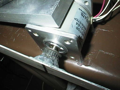
I used hot melt glue to attach the lever to the motor shaft, this glue breaks off cleanly when you are finished and is very handy in the lab. I also glued the motor to the bench and a weight on top of it. Not pretty, but workable.
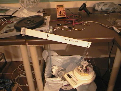
The finished setup in all its messy glory. The whole setup took me all of 10 minutes to make, and looks it! But it did the job and that's what matters. Note the battery as the counterweight on the lever, and the plastic food tub holding the weight. Also note the digital kitchen scales sitting on the attractive waste paper bin. As the lever and hanging tub was neutrally balanced, I could simply drop it on the scales in a second and read the weight of the contents of the tub. ie, the sample weight. This speeds up the tests, and is more convenient.
I used whatever was on the bench for weight, batteries, solder, etc. I also had a bag of paper clips, about 0.5g each, which were good to place in the tub for fine weight trimming. Obviously rice or screws or coins would all work.
Actually doing the tests
After the setup is complete, the measuring procedure is quite simple. The
motor coil or coils are connected to the variable power supply, through an
ammeter. This simple arrangement allows you to measure voltage, current,
(and obviously watts) and torque. We can test torque for different current
levels, test torque differences between unipolar and bipolar modes, test
differences between bipolar coils driven in series, half and parallel modes.
As we can calculate watts from volts x amps, we know the power dissipated by the motor for a given measured amount of torque. Things like the magnetic saturation point of the motor can be determined fairly easily by measuring the point where additional current increases don't make additional torque.
There are two ways to measure, you can load the tub with a known weight, giving a set torque, then reduce the voltage to the motor until the weight can no longer be held. This is handy for setting two motors to the same torque, or where you want to reach a specific torque figure and need to know the minimum volts/amp/watts to reach it. Alternatively you can set the voltage/current to a specific figure, like the motor maximum, or your driver maximum, or the maximum watts/heat dissipation, and then see what torque you get at the point where adding additional weight to the tub breaks the holding torque.
A third way is possible if you have access to a working motor driver, you can test the torque at differing run speeds, start speeds, and acceleration ramps. I will cover that later. Also, steppers change resistance slightly as they get hot, so you will need to adjust voltage slightly to keep current constant during the tests.
To end this chapter, I will give some of my test data from the first simple test on a standard "surplus" type stepper than can be bought for a few dollars.
Motor type: "Step-Syn" 23 frame, 5.1v, 1.0A, 10.2w, 6 wires, 50mm length

1.41A   7.73v    10.87w   4.55kg/cm (64.2oz/in) one half winding
1.93A   10.52v   20.30w   5.15kg/cm (72.6oz/in) one half winding

1.00A   10.86v   10.86w   5.15kg/cm (72.6oz/in) one full winding
1.20A   13.93v   16.72w   5.55kg/cm (78.3oz/in) one full winding

0.71A   7.62v    10.82w   5.95kg/cm (83.9oz/in) two full windings each
0.56A   5.96w    6.73w    5.15kg/cm (72.6oz/in) two full windings each
These figures show some interesting things if you know where to look. Like
increasing current from the rated 1A of the motor to 1.20A (a 20% current
increase) gave a 54% rise in heat dissipation (watts) but only produced a
7.8% increase in torque.
Also note that like most 23 frame motors, the torque for "two windings on"
is substantially more than the correct mathematical value of 141% of the
one winding torque. This is because the construction of the poles inside
the motor is optimised for maximum two winding on torque, which is the figure
the manufacturers like to publicise. This is great when your motor is stopped,
but to drive the motor to have good torque at speeds we need to keep currents
constant between full and half step positions.
-end-
Disclaimer This information was compiled and typed in a hurry. There may be errors. Use at your own risk, I make no guarantee as to the accuracy, safety, or effectiveness of anything contained within. All © Copyright R. Black 2001
Roman Black says:
http://romanblack.com/stepper.htm "I have built a test rig to measure both holding torque and shaft angle with high accuracy. This will let me measure (tune) motors for microstepping, to get exact torque and angle for every microstep.If anyone is interested I have done the measurement on a 5.1v 1A/phase bipolar 23-frame motor, it was WAY off the mathematic values that many microstepping drivers run at. Now I can tune my new CNC driver for perfect performance. Note that this motor is very similar to many common "surplus" steppers that we all use for projects"
See also:
| file: /Techref/io/stepper/measure-torque-rb.htm, 11KB, , updated: 2022/8/8 11:42, local time: 2025/5/1 06:18,
3.141.192.51:LOG IN
|
| ©2025 These pages are served without commercial sponsorship. (No popup ads, etc...).Bandwidth abuse increases hosting cost forcing sponsorship or shutdown. This server aggressively defends against automated copying for any reason including offline viewing, duplication, etc... Please respect this requirement and DO NOT RIP THIS SITE. Questions? <A HREF="http://www.sxlist.com/TECHREF/io/stepper/measure-torque-rb.htm"> High performance stepper articles. Part 2 - How to measure torque. Roman Black - Jan 2001</A> |
| Did you find what you needed? |
Welcome to sxlist.com!sales, advertizing, & kind contributors just like you! Please don't rip/copy (here's why Copies of the site on CD are available at minimal cost. |
|
The Backwoods Guide to Computer Lingo |
.